


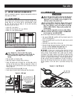


2.1 KNOW THE GENERATOR
Read the Owner’s Manual and Safety Rules before operating
this generator.
Compare the generator to Figure 3 to become familiarized with the
locations of various controls and adjustments. Save this manual
for future reference.
1. Run/Stop Switch
– Controls the operation of the generator.
2. Fuel Shut Off
– Valve between fuel tank and carburetor. Turn
off and run carburetor out of fuel for extended storage.
3. Panel LED's
– Provide illumination of the control panel while
the generator is operating.
4. 120/240 Volt AC, 20 Amp Locking Receptacle
– Supplies
electrical power for the operation of 120 and/or 240 Volt AC,
20 Amp, single-phase, 60 Hz, electrical lighting, appliance,
tool and motor loads.
5. 120 Volt AC, 20 Amp, GFCI Duplex Receptacle
– Supplies
electrical power for the operation of 120 Volt AC, 20 Amp,
single-phase, 60 Hz electrical lighting, appliance, tool and
motor loads. It also provides protection with an Integral
Ground Fault Circuit Interrupter, complete with a press to
"Test" and "Reset" button.
6. Circuit Breakers (AC)
– The 2-pole circuit breaker is rated
at 20 Amps; this protects the generator against electrical
overload.
7. Hourmeter
– Provides operating hours for Service Intervals.
8. PowerBar
– Indicates the amount of power being used from
the generator; each section is approximately 20%.
9. Fuel Tank
– Tank holds 4.5 U.S. gallons of fuel.
10. Fuel Gauge
– Shows fuel level in tank.
11. Handles
– Pivot and retract for storage. Press the spring-
loaded button to move handles.
12. Oil Fill
– Check oil level and add oil here.
13. Grounding Lug
– Ground the generator to an approved earth
ground here. See "Grounding the Generator" for details.
14. Muffler
– Includes the spark arrestor and quiets the engine.
15. Spark Plug
– Ignites Air/Fuel Mixture (Side panel must be
removed).
16. Engine Oil Filter
– Filters engine oil; see Section 3.1 for the
proper service intervals.
17. Choke
– Used when starting a cold engine.
18. Air Cleaner
– Filters intake air as it is drawn into the engine.
19. Oil Drain
– Drain valve to remove used oil from the engine
crankcase.
20. Recoil Starter
– Use to start engine manually.
21. Carbon Canister
- Absorbs fuel tank vapors.
22. Roll Over Valve
- Passes fuel vapors to the carbon canister.
23. Recovery Hose
- Installed between the carbon canister and
the Roll Over Valve.
Figure 3 – Generator Locations and Controls
23
5
Operation


