


Hardware Installation & Configuration
Gemini 720is Imaging Sonar
Document: 0703-SOM-00002, Issue: 1
16
© Tritech International Ltd.
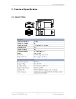
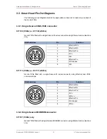
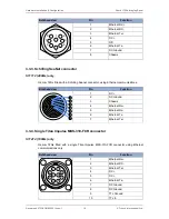
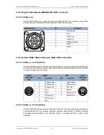
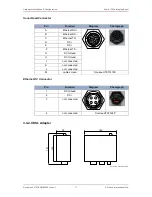
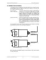
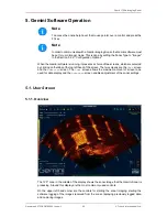
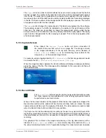
MAIN
AUX
MAIN
Bulkhead
view
Pin
Function
Pin
Function
AUX
Bulkhead
view
1
Ethernet Rx+
1
RS232 Rx /
RS485 B
2
Ethernet Rx-
2
RS232 Tx /
RS485 A
3
Ethernet Tx+
3
24V DC +
4
DC +
4
0V DC
5
VDSL +
5
RS232 / TTL
Ground
6
Ethernet Tx-
7
DC Ground
5
6
4
1
2
3
7
8
8
VDSL -
6
TTL In
6
5
4
1
2
3
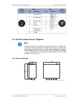
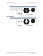
3.4. Surface Adapter Pin-out Diagrams
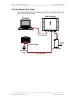
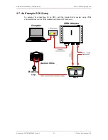
Note
For all system types the connection to the surface computer or IT infrastructure
from the Gemini Hub, Ethernet or VDSL adapter should be via a shielded Cat5e
cable fitted with an RJ45 connector. The 72V VDSL Adapter Unit can also be
used in applications where long length power and communications is desirable
- for more information see the associated Product Manual:
0713-SOM-00003
available at
www.tritech.co.uk
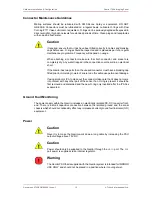
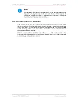
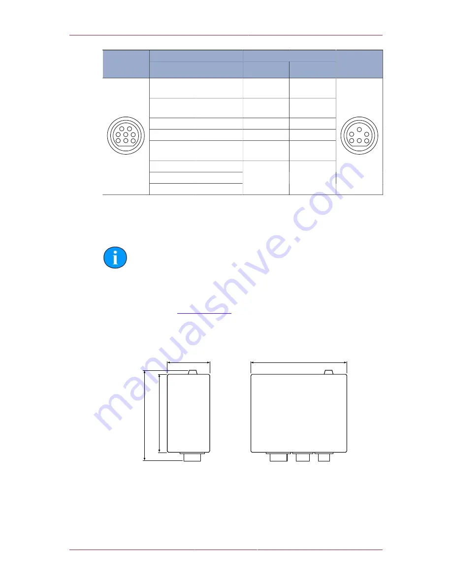
3.4.1. Ethernet Adapter
Not to scale, dimensions in mm.
1
3
0
1
5
1
70
160


