


Hardware Installation & Configuration
Gemini 720is Imaging Sonar
Document: 0703-SOM-00002, Issue: 1
15
© Tritech International Ltd.
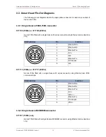
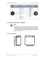
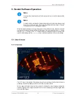
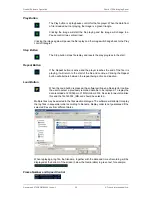
3.3.5. Single Titan Impulse MKS(W)-307-FCR connector
S11415 (1000m) only
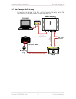
Gemini 720is fitted with a single Titan Impulse MKS(W)-307-FCR connector using VDSL
communications. An auxiliary RS232 input can be fed into the sonar.
Bulkhead view
Pin
Function
1
DC Ground
2
DC +
3
RS232 Rx
4
RS232 Tx
5
RS232 Ground
6
VDSL +
4
1
2
5
3
6
7
7
VDSL -
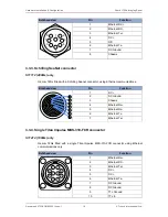
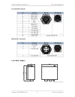
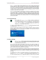
3.3.6. Seacon 5506-1508 and Seacon 5506-1506 connectors
S11127 (1000m) or S11128 (4000m)
Gemini 720is fitted with two Seacon 55 series connectors. The main connector uses Ethernet
communications with the auxiliary connector providing an additional Ethernet communication
line and regulated 24V DC output.
MAIN
AUX
MAIN
Bulkhead
view
Pin
Function
Pin
Function
AUX
Bulkhead
view
1
Ethernet Rx+
1
Ethernet Rx+
2
Ethernet Rx-
2
Ethernet Rx-
3
Ethernet Tx+
3
24V DC +
4
DC +
4
0V DC
5
N/C
5
Ethernet Tx+
6
Ethernet Tx-
7
DC Ground
5
6
4
1
2
3
7
8
8
N/C
6
Ethernet Tx-
6
5
4
1
2
3
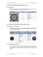
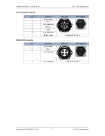
S11017 (1000m) or S11027 (4000m)
Gemini 720is fitted with two Seacon 55 series connectors. The main connector uses Ethernet
communications with the auxiliary connector allowing either RS232 or RS485 (software
selectable) communications to an attached device. A regulated 24V DC output is also
available.


