background image


Rev. 00  03/22


50  

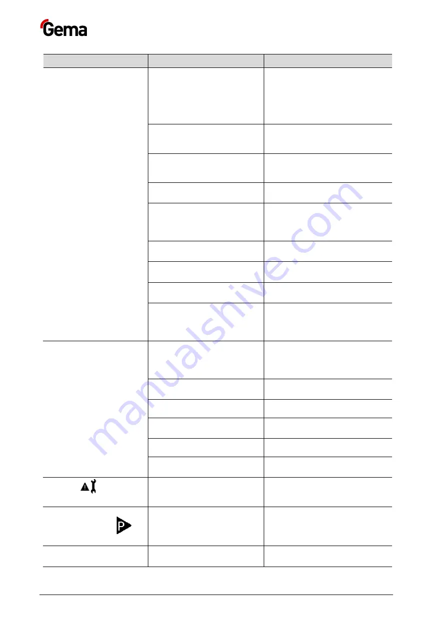
  Fault clearance 

OptiFeed BigBag (FPS16) 

Incident 

Causes 

Corrective action 


Service life of the pinch valve 
has expired (defective) 

–  Replace pinch valve and 

associated protective filter 
element 

–  Blow off or replace 

contaminated hose 
connection 


Filter elements of the powder 
chamber tend to become 
clogged 

Run the cleaning program, replace 
the filter elements 


Lifetime of the filter elements in 
the powder chamber expired 
(clogged) 

Replace the filter elements 


Powder hoses tend to clog due 
to sintering 

Clean or replace the powder hoses 


The conveying hose or suction 
hose is clogged 

Empty the powder hose with 
compressed air or manually 
(

Warning


– powder will be 

expelled!) 


Conveying pressure desired 
value C0 incorrectly set 

Set correctly () 


Vacuum desired value C1 
incorrectly set 

Set correctly () 


Pinch valve pressure desired 
value C2 incorrectly set 

Set correctly () 


Oil or water in the system 

Do not use the pump before 
ensuring that oil or water will be 
separated before entering into the 
pump, otherwise contact Gema 

Indicator on powder pump 
does not light up 

No operating voltage 

The corresponding voltage must 
be present at connection 

2.1

: PP07 

= +24 VDC; PP07-S = 110-240 
VAC 


Indicator defective or 
incorrectly connected 

Replace/connect correctly 


Main board is defective 

Replace/send in for repair 


Power pack is defective (PP07-
S) 

Replace 


Fuse is defective (PP07-S) 

Replace 


Main switch is defective (PP07-
S) 

Replace 

Indicator 

 flashes 

The parameter memory test 
was erroneous 

Reset to the default values: 
 Press for 5 seconds 
Then set parameters, if necessary 

Powder pump is not 

conveying, indicator 

 is 

not flashing 

No 

Pump on

 control signal 

A control signal must be applied at 
connection 

2.1 

PIN 2 

If the LEDs on the valve 
connectors do not light up, the 

Replace pump control or send it in 
for repair 

Summary of Contents for FPS16

Page 1: ...Rev 00 1017 588 EN Operating instructions and Spare parts list Fresh powder system OptiFeed BigBag FPS16 Translation of the original operating instructions ...

Page 2: ...d trademarks of Gema Switzerland GmbH All other product names are trademarks or registered trademarks of their respective holders Reference is made in this manual to different trademarks or registered trademarks Such references do not mean that the manufacturers concerned approve of or are bound in any form by this manual We have endeavored to retain the preferred spelling of the trademarks and re...

Page 3: ...ic data 17 Dimensions 17 Container specifications big bag 18 Conveying performance 18 Environmental conditions 18 Sound pressure level 19 Rating plate 19 Structure 20 Overall view 20 Versions 21 Support 21 Lifting device for large containers 21 Fluidizing suction unit 21 Lifting device for fluidizing suction unit 21 Vibrating plate 22 Control 22 Control cabinet 22 Control module 23 Powder pump 23 ...

Page 4: ...check 33 Operation 35 Operation 36 Powder hose rinsing 36 Color change 37 Decommissioning Storage 39 Shutdown 39 Storage conditions 39 Hazard notes 39 Type of storage 39 Storage duration 39 Space requirements 39 Physical requirements 39 Maintenance during storage 40 Maintenance schedule 40 Maintenance works 40 Maintenance Repairs 41 General information 41 Interval 42 Daily maintenance 42 Weekly ma...

Page 5: ...ents on personnel carrying out the work 53 Disposal regulations 53 Materials 53 Spare parts list 55 Ordering spare parts 55 FPS16 Fresh powder system spare parts list 56 FPS16 Fresh powder system spare parts 57 Fluidizing suction unit 58 Fluidizing suction unit 59 ...

Page 6: ......

Page 7: ...Manual Please keep this Manual ready for later use or if there should be any queries Safety symbols pictograms The following warnings with their meanings can be found in the Gema instructions The general safety precautions must also be followed as well as the regulations in the relevant instructions DANGER Indicates a hazardous situation which if not avoided will result in death or serious injury ...

Page 8: ... of Safety Notes Every note consists of 4 elements Signal word Nature and source of the danger Possible consequences of the danger Prevention of the danger SIGNAL WORD Nature and source of the hazard Possible consequences of the danger Prevention of the danger Presentation of the contents Figure references in the text Figure references are used as cross references in the descriptive text Example T...

Page 9: ...elopment manufacture and configuration are described in the EC declaration of conformity and in the manufacturer s declaration WARNING Working without instructions Working without instructions or with individual pages from the instructions may result in damage to property and personal injury if relevant safety information is not observed Before working with the device organize the required documen...

Page 10: ...substances outside of our guidelines then Gema Switzerland GmbH should be consulted Start up i e the execution of intended operational tasks is forbidden until it has been established that this product has been set up and wired according to the guidelines for machinery The standard Machine safety must also be observed Unauthorized modifications to the product exempt the manufacturer from any liabi...

Page 11: ...rring processes For further information see the more detailed Gema safety regulations WARNING These general safety regulations must be read and understood in all cases prior to start up General information This product is built to the latest specification and conforms to the recognized technical safety regulations and is designed for the normal application of powder coating Any other use is not co...

Page 12: ... plug connections between the powder spraying equipment and the mains should only be removed when the power supply is switched off All maintenance activities must take place when the powder spraying equipment is switched off The product may not be switched on until the booth is in operation If the booth stops the product must switch off too Explosion hazard The control units for the spray guns mus...

Page 13: ... remain grounded The appropriate measuring devices must be kept ready in the workplace in order to check the grounding The floor of the coating area must conduct electricity normal concrete is generally conductive The supplied grounding cable green yellow must be connected to the grounding screw of the electrostatic manual powder coating equipment The grounding cable must have a good metallic conn...

Page 14: ...pair The plug connections between the powder spraying equipment and the mains should only be removed when the power supply is switched off As far as it is necessary the operating firm must ensure that the operating personnel wear protective clothing e g facemasks A dust mask corresponding to filter class FFP2 or N95 at minimum must be worn during any cleaning work The operating personnel must wear...

Page 15: ...ntainer and in accordance to the consumption in the coating plant The powder transport is automatically switched on and off by messages from the level sensor in the powder container The powder is aspirated in pulses by a vacuum and subsequently transported with conveying air The fresh powder system will also operate in combination with the OptiFeed PP07 powder pump or other Gema models with suitab...

Page 16: ...as intended use The manufacturer is not responsible for any incorrect use and the risks associated with such actions are assumed by the user alone For a better understanding of the interrelationships in powder coating it is recommended that the operating instructions for all other components be read as well so as to be familiar with their functions too Reasonably foreseeable misuse Operation witho...

Page 17: ...eed BigBag FPS16 Compressed air connection 1 4 Min input pressure 6 bar Max input pressure 8 bar Max compressed air consumption 0 5 Nm h for lifting procedure 12 Nm h for each PP0x Powder pump 0 5 Nm h for fluidizing Max water vapor content of the compressed air 1 3 g m Max oil vapor content of the compressed air 0 1 mg m Dimensions OptiFeed BigBag FPS16 Width 1670 mm Height 3885 mm Depth with lar...

Page 18: ...6 25 m 3 5 kg min conveying performance Hose diameter Transport side NW 16 mm Suction line up to 5 m Material to be conveyed Coating powder Remaining quantity 5 of the original container content The indicated values are guide values for each pump possible deviations are dependent on the powder type and the hose length The compressed air consumptions are listed in the corresponding operating manual...

Page 19: ...nts were taken at the most frequent operator positions and at a height of 1 7 m from the ground The specified value during normal operation is applicable only for this product itself and does not take into account external noise sources or cleaning impulses The specified value during cleaning operation requires the wearing of ear protection The sound pressure level may vary depending on the produc...

Page 20: ...description OptiFeed BigBag FPS16 Structure Overall view Fig 3 Structure 1 Fluidizing suction unit 2 Control 3 Powder pump 4 Support 5 Vibrating plate 6 Lifting device for container 7 Lifting device for fluidizing suction unit ...

Page 21: ...be ensured The crossbeam can be installed depending on the container on three different heights Lifting device for large containers The lifting device for large containers consists of the hang up plate and two pneumatic cylinders The operation and the control take place by the attached control cabinet Fluidizing suction unit The fluidizing suction unit enables the loosening of the powder in the co...

Page 22: ...ption 1 Main switch The complete control unit is disconnected from the mains with the main switch 2 Vibrator ON OFF This switch turns the vibration plate on off 3 Big Bag empty This red indicator lamp illuminates if the powder flow sensor does not detect powder during a defined time Now the large powder container must be checked by the operating personnel and probably be changed 4 Conveying ready ...

Page 23: ...fted manually and can then be blown off and cleaned with compressed air Attention large dust formation possible 5 Conveying ready This indicator light indicates that the system is ready for conveying Control module Fig 6 Control module 1 Power pack 2 Main module 3 Additional module Powder pump The laterally attached powder pump sucks the powder if required by the fluidizing suction unit and ensure...

Page 24: ...wer end of the tube Thereby the area around the suction tube is partially fluidized the powder obtains fluid like characteristics and will be sucked into the tube The vibration of the vibrating plate causes an even powder level this prevents the suction of false air through air craters That way the powder can be used almost entirely optimum powder utilization Powder flow detection The powder trans...

Page 25: ...ed to the floor Connection The equipment is supplied ready for use by the manufacturer Just a few cables and hoses must be connected 1 Ensure the grounding of the equipment 2 Connect the powder hose 3 Connect fluidizing suction unit with compressed air hose 4 Connect the compressed air 5 Establish electrical connection see wiring diagram The compressed air must be free of oil and water Electrical ...

Page 26: ...ve I6 Reserve I7 Analog input 0 10 V pressure sensor for pump 1 I8 Analog input 0 10 V pressure sensor for pump 2 Main module outputs Output Description Q1 main solenoid valves Q2 Solenoid valve lift cylinder Q3 Warning lamp no powder Q4 Potential free contact no powder max voltage 230 VAC Additional module inputs Entry Description I1 I4 Reserve Additional module outputs Output Description Q1 Conv...

Page 27: ... in accordance to the specifications All compressed air consumers will be supplied by the control unit Fig 7 Description 1 Lift lower 2 Fluid air P min 0 5 bar 3 Compressed air supply of pinch valves FPS16 2 version only P max 3 0 bar Powder connections The powder hose must be connected according to the corresponding powder pump s ...

Page 28: ...malfunction occurs see the troubleshooting guide as well as the Powder pump operating manual Fig 8 The remainder of the start up procedure for the Powder pump is explicitly described in the corresponding operating instructions chapter Initial start up and Daily start up ...

Page 29: ...r The fluidization and vibration characteristics of the powder are dependent on the powder type the air humidity and the ambient temperature The fluidization and the vibration start by switching on the powder feed see also Functional check Parameterization The various time sequences can be easily set and adapted to all plant specific requirements by the aid of a simple menu control unit Read caref...

Page 30: ... unit Press OK The first block B1 appears Press the key the block B2 appears Select Block B2 to B4 with the triangular arrow key Press OK Select and modify the values with the arrow keys Press OK The values are saved and the block B2 appears Quit the program mode with the ESC key and return to the normal display The control unit continues to process the program in the Parameterization operating mo...

Page 31: ...0 0 secs B016 Debouncing of B001 T 10 0 secs The pressure monitoring must indicate no powder for a defined duration until the signal will be evaluated B017 Debouncing of B014 T 3 0 secs The no powder signal must be present for a defined duration For the adjustment and the operation of the powder transport the corresponding powder pump documentation must be observed Powder flow detection Overview I...

Page 32: ...e in the powder hose 4 Threshold value down variable 5 Threshold value reached Powder flow OK Craters in the powder container container empty Fig 10 1 Craters in the powder container container empty 2 Pump 3 Backpressure in the powder hose 4 Threshold value down variable 5 Threshold value not reached Powder flow not OK ...

Page 33: ...al free contact is set which can be evaluated by an external reporting device Adjusting the threshold values Lower threshold value The lower threshold depends of the length of the conveying distance and the filling by the powder pump Example Length of the feed section Default value Action 15 m 150 OK 5 m approx 80 adjust Upper threshold value The upper threshold value limits the correct functional...

Page 34: ...Rev 00 03 22 34 Start up OptiFeed BigBag FPS16 ...

Page 35: ...ng damage caused by sound overexposure Peak noise levels for a short time up to 95 db A occurring during the cleaning process may cause hearing damage Wear adequate hearing protection e g ear muffs per EN 352 1 CAUTION Large dust formation possible If no dust mask or one of an insufficient filter class is worn when cleaning the product then the dust that is stirred up from the coating powder can c...

Page 36: ...tion of the safety straps on the bolts 4 Open the top of the container opening to insert the fluidization suction unit 5 Fit the vibrating plate 6 Create the readiness for powder conveying by the Automatic switch position 7 Lower the fluidizing suction unit manually and slowly into the large powder container 8 Set conveying parameters Powder hose rinsing In order to prevent the hose from clogging ...

Page 37: ...t that the partially emptied container is well locked for storage The following describes an extreme color change light to dark 1 Empty the powder hose by removing the fluidizing suction unit from the powder box when the conveying is activated 2 End powder feed 3 Stop vibration of the powder box 4 Activate cleaning mode see OptiFeed 4 0 operating manual The automated cleaning procedure is started ...

Page 38: ...Rev 00 03 22 38 Operation OptiFeed BigBag FPS16 ...

Page 39: ...cal and pneumatic connection Storage conditions Hazard notes There is no danger to personnel or the environment if the unit is stored properly Type of storage For safety reasons the product should only be stored in a vertical position Storage duration If the physical conditions are maintained the unit can be stored indefinitely Space requirements The space requirements correspond to the size of th...

Page 40: ...e during storage Maintenance schedule No maintenance plan for the equipment is necessary The equipment fitted with powder pump OptiFeed 4 0 must be serviced after a long standstill period 1 year Maintenance works During long term storage periodically perform a visual check ...

Page 41: ...alterations to the product are not permitted for safety reasons and exclude the manufacturer s liability for any resulting damage Regular and conscientious cleaning and maintenance increase the service life of the product and ensure consistent high coating quality The parts to be replaced during maintenance work are available as spare parts These parts can be found in the appropriate spare parts l...

Page 42: ...ry With other powder color tone See chapter Color change on page 37 Weekly maintenance 1 Visual check for possible damages see also the spare parts list of the powder pump 2 Clean the fluidizing suction unit and pump Place the fluidizing suction unit back into the powder shortly before restarting operation 3 Check the grounding connections with the coating booth the suspension devices of the work ...

Page 43: ...ssed air This is where the equipment s main compressed air connection is located Replacing the filter element 1 Unscrew the filter glass on the filter unit 2 Remove the complete filter element Fig 11 Symbol image for maintenance of a filter element 3 Replace the filter element 4 Clean the filter glass on the inside and install it again ...

Page 44: ... connecting cables and hoses The corresponding parts should be replaced immediately if any damage to cables or hoses is discovered All plugs must be properly tightened Repair work In the event of malfunctions or faults the product must be checked and repaired at an authorized Gema service location The repairs must only be performed by an authorized specialist Improper interventions can result in s...

Page 45: ...pport 5 Vibrating plate 6 Lifting device for container 7 Lifting device for fluidizing suction unit see chapter Software error diagnostics on page 47 Problem error malfunction Cause Procedures remedy Vibration not running Vibration motor not connected or defective Connect the cables Replace the vibration motor Fluidization not running Compressed air not present Ensure the compressed air supply ...

Page 46: ...on suction unit not lowered Vibrating plate not functioning or NOT SWITCHED ON Check connection Replace vibrator fluidizing air not present Fluidization air line not plugged into the suction unit Fluidizing air supply is bent Adjust the fluidizing air with the pressure regulator in the control cabinet Plug in fluidizing air hose Lay out fluidizing air hose as straight as possible Too much fluidizi...

Page 47: ...s for this powder pump Code Description Criteria Remedy Power supply H20 Voltage supply error Mainboard Mainboard defective Contact Gema Service H21 Supply undervoltage Power pack defective or overloaded Contact Gema Service EEPROM equipment memory H24 EEPROM content invalid EEPROM error Contact Gema Service H25 Timeout during EEPROM writing EEPROM error Contact Gema Service H26 Values not correct...

Page 48: ...ntact Gema service Display module H50 Firmware update for display required The firmware installed on the display is not supported Replace or update display Throttle motors H60 Transport air reference position not found Throttle motor or needle jammed limit switch defective error in motor throttle Contact Gema Service H61 Vacuum reference position not found Throttle motor or needle jammed limit swi...

Page 49: ...ction Powder pump does not convey Compressed air supply failed or pressure too low Check the compressed air source ensure an air pressure of 6 8 bar check the pressure gauge of the local pressure regulator No control signal Check the control cable or control signals Powder not present Refill powder No fluidization in the suction zone Ensure the fluidization or set correctly Conveying hose is clogg...

Page 50: ...tly Pinch valve pressure desired value C2 incorrectly set Set correctly Oil or water in the system Do not use the pump before ensuring that oil or water will be separated before entering into the pump otherwise contact Gema Indicator on powder pump does not light up No operating voltage The corresponding voltage must be present at connection 2 1 PP07 24 VDC PP07 S 110 240 VAC Indicator defective o...

Page 51: ...03 22 OptiFeed BigBag FPS16 Fault clearance 51 Incident Causes Corrective action Powder pump is not conveying indicator is flashing pump control or corresponding valve is defective Replace the defective valve ...

Page 52: ...Rev 00 03 22 52 Fault clearance OptiFeed BigBag FPS16 ...

Page 53: ... by Gema the instructions in the respective manufacturer s documentation must be observed Disposal regulations The product must be disassembled and disposed of properly at the end of its service life When disposing of the product the applicable local and regional laws directives and environmental regulations must be complied with Materials The materials must be sorted according to material groups ...

Page 54: ...Rev 00 03 22 54 Disposal OptiFeed BigBag FPS16 ...

Page 55: ...ordering cable or hose material the required length must also be given The spare part numbers of this bulk stock is always marked with an The wearing parts are always marked with a marked All dimensions of plastic hoses are specified with the external and internal diameter Example Ø 8 6 mm 8 mm outside diameter o d 6 mm inside diameter i d WARNING Use of non original Gema spare parts When using th...

Page 56: ...Elbow joint 1 4 1 4 222 674 7 Double nipple 1 4 1 8 242 209 8 Check valve 1 8 with fix throttle 1003 946 9 Rubber strap 1002 616 10 Roller 1002 490 11 Sliding bearing 1004 037 12 Plastic tube Ø 8 6 mm 103 756 13 Klett Cable Bride 1023 370 14 Hose holder 1023 592 15 Wire rope 103 870 16 Spring hook 1013 413 17 Round sling 1012 173 18 Grounding cable complete 1011 888 19 Vibrator 261 980 20 Steel bo...

Page 57: ...Rev 00 03 22 OptiFeed BigBag FPS16 Spare parts list 57 FPS16 Fresh powder system spare parts Fig 13 Spare parts ...

Page 58: ...49 4 Connection plug 1006 556 5 Elbow joint 1 8 1 8 237 604 6 O ring Ø 29x2 mm 215 252 7 External tube 1023 146 8 Internal tube 1023 147 9 Suction ring 1023 149 10 Fluidring 1023 155 11 Quick release connection NW5 Ø 8 mm 203 181 12 Plastic tube Ø 8 6 mm 103 756 13 Hose connection complete incl pos 14 1023 156 14 O ring Ø 20x2 mm 1017 809 15 Powder hose Ø 23 16 mm 1010 040 Please indicate length W...

Page 59: ...Rev 00 03 22 OptiFeed BigBag FPS16 Spare parts list 59 Fluidizing suction unit Fig 14 FPS16 Fresh powder system fluidizing suction unit ...

Page 60: ......

Page 61: ...17 Environmental conditions 18 F Fault clearance 45 Figure references in the text 8 I Intended use 15 M Maintenance 41 Maintenance during storage 40 O Operation 35 P Parameters 31 Periodic checks 44 Pictograms 7 Pneumatic data 17 Powder flow detection 31 Presentation of the contents 8 Product description 15 Product specific safety information 11 R Rating plate 19 Repair work 44 Repairs 41 S Safety...

Page 62: ...Rev 00 ...

Reviews: