Form No.
907389
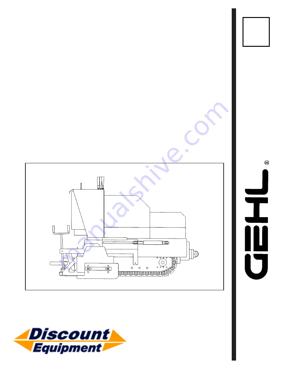
OPERATOR’S MANUAL
1639/1649
PowerBox
Self Propelled
Paver
www.discount-equipment.com
Discount-Equipment.com
Page 1: ...Form No 907389 OPERATOR S MANUAL 1639 1649 PowerBox Self Propelled Paver www discount equipment com D i s c o u n t E q u i p m e n t c o m...
Page 2: ...ie Terex JLG MultiQuip Mayco Toro Stone Diamond Products Magnum Airman Mustang Power Blanket Nifty Lift Atlas Copco Chicago Pneumatic Allmand Brothers Essick Miller Spreader Skyjack Lull Skytrak Tsuru...
Page 3: ...ations 58 11 Maintenance Log 62 Index 66 Standard Hardware Torque Data 68 International Symbols Inside Back Cover IDENTIFICATION INFORMATION Write your Gehl PowerBox Model 1639 or 1649 and Serial Numb...
Page 4: ...ep it with the unit at all times If this machine is resold GEHL Company recommends that this Manual be given to the new owner Right and left are determined from a position standing on the Screed Platf...
Page 5: ...R STEERING SCREED HOPPER BACK WALL DRIVE TRACK EA SIDE PROPANE TANK HYDRAULIC RESERVOIR LOWER FRAME ENGINE HYD PUMP SCREED ADJUST SCREW EA SIDE SPRAY DOWN HOSE EA SIDE RIGHT HAND CONTROL LEVERS Printe...
Page 6: ...Screed Maximum Variable Crown Invert 2 in 2 in 51 mm 51 mm Width 12 in 12 in 305 mm 305 mm Hydraulic Vibrator Std 83 Hz Std 83 Hz 5000 cy min 5000 cy min Heat Medium Exhaust Standard Standard Heat Me...
Page 7: ...Fine Tune Steering Valve Std Std Maximum Ground Speed 130 FPM 130 FPM 39 7 mpm 39 7 mpm Hydraulic System Variable Hydrostatic Drive Pump Maximum Flow 27 GPM 27 GPM 102 Ltrs M 102 Ltrs M Variable Hydr...
Page 8: ...in 0 1 2 in 0 13 mm 0 13 mm Maximum Variable Paving Depth 6 in 6 in 152 4 mm 152 4 mm Gravity Feed Hopper Capacity 6 Ton 6 Ton 5436 kg 5436 kg Hydraulic Feed Augers 2 2 Hydraulic Material Flow Gates 2...
Page 9: ...ct with Drive Motors in neutral No hydraulic system leaks when under pressure Listen for abnormal noises or vibrations if detected deter mine their cause and repair as necessary I acknowledge that pre...
Page 10: ...r the Hopper and Screed Assembly to the full down position 3 Place controls in Neutral 4 Move the Throttle to low idle 5 Shut off the Engine and remove the Key ONLY when you have taken these precautio...
Page 11: ...YS lower the Hopper to full down position shut off the Engine and place all controls in neutral BEFORE leaving the machine z ALWAYS position the Safety Props when leaving the Hopper raised for inspect...
Page 12: ...cations Nameplates Markings And Capacities z Modifications and additions which affect capacity or safe operation shall NOT be performed without the manufacturer s prior written approval Where such aut...
Page 13: ...SAFETY Continued Printed In U S A 13 907389 AP297 D i s c o u n t E q u i p m e n t c o m...
Page 14: ...SAFETY Continued 907389 AP297 14 Printed In U S A D i s c o u n t E q u i p m e n t c o m...
Page 15: ...s be returned to the OFF position between starting attempts The Battery Charge and Engine Oil Pressure Model 1649 Indicators should activate when the key is turned to the RUN position Pre Heat Glow Pl...
Page 16: ...Engine Oil Pressure 1649 2 Throttle 5 Keyswitch 9 Spray Down Pump Switch 3 Battery Gauge 6 Glow Plug Indicator 1649 10 Hourmeter 7 Water Temperature Gauge 1649 11 Exhaust Diverter 1649 MODELS 1649 SHO...
Page 17: ...should be OFF During starting and when the Engine is NOT running this Lamp will be ON NOTE If this lamp comes ON during normal operation with the Engine running STOP the Engine immediately After allo...
Page 18: ...decrease speed Place the Lever in neutral when not operating Track Travel These two Levers control the Track Drive Motors for forward and rearward movement and also turning of the Paver Both Levers ar...
Page 19: ...wide the Side Gates should be closed This is achieved by closing the Shut Off Gates with the Side Gate Valve ON then turn ing the Side Gate Valve to the OFF position before re opening the Shut Off Gat...
Page 20: ...aving width beyond 9 feet One Lever controls each Extension Move the Lever FORWARD to shift the Extension inword Move the lever BACK to shift the Extension outward The Right Extension Lever is mechani...
Page 21: ...NOTE All accessories are field installed unless otherwise noted Information and parts for field installing of all of the accessories will be provided by the Factory or GEHL Paver dealers Cut Off Plat...
Page 22: ...se the Tank Valve and the valves on both Handles 4 Slowly open Tank Valve 5 Adjust Regulator 15 20 psi 6 Remove one burner from the Burner Tube Support and light with a Striker Place Burner back into...
Page 23: ...e Valve for cold Engine starts If re starting a warm Engine little or no choking is required 3 Turn the Key to START position When Engine starts release the Keyswitch and it will automati cally return...
Page 24: ...afety Guards and Covers Hands On Check 1 Check the Fuel Gauge Fill the Reservoir before paving and as necessary 2 Check the Engine Oil Level and replenish as nec essary 3 Check the cooling air intake...
Page 25: ...s of the desired paving thickness 4 Manually adjust the Screed Depth Control Screws up or down as required to a neutral or free posi tion Slowly turn the Screws toward the up posi tion until a slight...
Page 26: ...10 to 15 minutes pave 12 to 18 inches further and again leave a small head of asphalt Repeat in 10 to 15 minute intervals using asphalt remaining in the Hopper until next load arrives If the Paver is...
Page 27: ...the windrow CAUTION Do NOT attempt to move HOT asphalt mix with your hands or feet Contact can cause serious skin burns asphalt opening both Flow Gates as the windrow asphalt begins to run thin If th...
Page 28: ...on from the two tiedown chains on the rear of the Paver 4 Fig 12 Remove the chains from both tiedown points on the rear of the Paver 5 Move the Screed Control Lever to up position and hold until Scree...
Page 29: ...rd allowing the Paver to move slowly up the ramps The operator should ride on the Paver with a hand on both Track Control Levers at all times to stop the Paver if travel is not straight 7 Immediately...
Page 30: ...coat with heavy very high flash point grease to prevent rusting THEFT DETERRENTS THE CERTAINTY OF APPREHENSION IS A STRONG DETERRENT TO THIEVERY OF CON STRUCTION EQUIPMENT GEHL has recorded Part Numbe...
Page 31: ...nation Replace any missing or damaged fittings To minimize dirt build up avoid excessive greasing Chapter 7 LUBRICATION CAUTION NEVER attempt to lubricate or service this unit when any part of the mac...
Page 32: ...ol Linkage 2 ea 9 Change Engine Oil Filter Every 2000 Hours 10 Change Hydraulic Reservoir Fluid 11 Clean or Replace Hydraulic Sump Strainer Replacement Filters Chart 1649 Diesel Engine Oil Filter Elem...
Page 33: ...E LUBRICATION CHART Engine Oil Gear Oil Hydraulic Oil Grease 2000 HOURS 500 HOURS 250 HOURS 40 100 HOURS 10 HOURS 1 9 8 2 2 7 5 10 11 4 6 3 Printed In U S A 35 907389 AP297 D i s c o u n t E q u i p m...
Page 34: ...y be as much Linkage for dual controls binding Free up linkage as 1 to 2 ft in 100 ft of travel under little or no Tracks not properly aligned Correct alignment load conditions Soft or uneven terrain...
Page 35: ...y surface See Causes 1 3 4 long waves 5 Overcorrecting Thickness Control Make more moderate corrections as Screws infrequently as possible 6 Running hopper empty between Stop Paver before head of mate...
Page 36: ...s 2 Improper rolling operation Decrease speed 3 Improper mix design aggregate See Asphalt Paving Manual 4 Improper mix design asphalt See Asphalt Paving Manual 5 Mix segregation Asphalt plant mixing t...
Page 37: ...Causes 7 8 Screed not responding See Causes 6 11 12 to correction Auger shadows See Causes 3 5 Poor pre compaction See Causes 1 11 12 Poor longitudinal or See Causes 2 12 transverse joint Transvers cr...
Page 38: ...Using pressure gauge readjust pressure Lever or link bent Remove and replace Spool bent Replace entire valve assembly Return spring failing Replace spring Return spring or cap misaligned Loosen realig...
Page 39: ...amaged Disassemble inspect for damage 10 Relief valve stuck open Remove clean or replace 11 Damaged check valve Dissassemble and check if valve is faulty or damaged System noisy 12 Air in system Low o...
Page 40: ...position Turn Keyswitch to START position Speed control not in OFF position Move speed control to OFF position Faulty wiring and or terminations or Troubleshoot circuit and repair Fuse open Faulty Sta...
Page 41: ...replace crankcase oil with proper viscosity oil Engine is cold See OEM Engine Manual Engine cuts out Out of fuel Replenish fuel abruptly Fuel Filter is clogged and or air is Clean or replace Fuel Filt...
Page 42: ...g center for disposal Do NOT pour them onto the ground or into a drain DEALER SERVICES The following areas of internal components service replacement and operating adjustments should only be attempted...
Page 43: ...ers away if access Covers are removed After servicing check the work performed NO parts left over etc Install all guards covers and reconnect the Battery SPRAY DOWN ASPHALT CONTACT AREAS The following...
Page 44: ...e stopped for ten 10 minutes or more remove the Engine Dipstick Wipe it clean re insert it and remove to obtain a reading If the oil level is down or below the ADD mark fill with the required amount o...
Page 45: ...attery Filler Caps and make sure that electrolyte solution is up to the proper level In addition place a clean cloth over the uncapped filler holes to prevent the electrolyte solution from overflowing...
Page 46: ...eep flames or sparks away from the Battery area Make sure Battery is charged in a well ventilated area NEVER lay a metal object on top of a Battery as a short circuit can result Battery acid is harmfu...
Page 47: ...etween the End Cap and the Main Body LUBRICATE WEEKLY GREASE POINTS NOTE Weekly lube is to be done in conjunction with daily lube requirements of this chapter Refer to the Lubrication chapter of this...
Page 48: ...h previous lube requirements of this chapter CHANGE ENGINE OIL FILTER The Engine Oil Filter should be changed at every other oil change interval Remove and discard the throw away Filter canister Wipe...
Page 49: ...Only an authorized Engine dealer can perform WARRANTY Service on the Engine CHANGE RADIATOR COOLANT 1649 Diesel Drain flush and refill the cooling system as follows NOTE DO NOT discharge onto ground...
Page 50: ...y debris Re install the Strainer Drain Plug and reconnect the suction hose 4 Fill the Reservoir with fresh hydraulic oil Follow specifications found in the Lubrication capater of this manual NOTE Hydr...
Page 51: ...ne coolant is either completely drained from the Radiator and Engine block or that the amount of anti freeze in it is adequate to keep the coolant from freezing Refer to the separate Engine manu al pr...
Page 52: ...1639 1649 Hydraulic Schematic A B C D E 907389 AP297 54 Printed In U S A D i s c o u n t E q u i p m e n t c o m...
Page 53: ...1639 1649 Hydraulic Schematic A B C D E Printed In U S A 55 907389 AP297 D i s c o u n t E q u i p m e n t c o m...
Page 54: ...1639 Electrical Schematic 907389 AP297 56 Printed In U S A D i s c o u n t E q u i p m e n t c o m...
Page 55: ...1649 Electrical Schematic Printed In U S A 57 907389 AP297 D i s c o u n t E q u i p m e n t c o m...
Page 56: ...ing proper position and alignment Slowly peel off the other portion of the backing paper while applying hand pressure to smooth out decal sur face to apply a die cut decal first remove the backing pap...
Page 57: ...25 P471425 4 PowerBox Logo 2 ea P470323 P470323 5 WARNING Pinch Point 3 ea L65927 L65927 6 Floor Safety Prop 2 ea P210200 P210200 7 On Off Arrows 2 ea P207300 P207300 8 PowerBox Lettering 2 ea P204030...
Page 58: ...04100 P204100 13 Auger Control 1 ea P471640 P471640 14 LH 7 Stack Controls 1 ea P204017 P204017 15 DANGER Rotate Components 1 ea L65924 L65924 16 WARNING Pinch Point 1 ea L65927 L65927 17 WARNING Jump...
Page 59: ...15 8 16 22 23 22 3 17 8 24 20 19 5 7 6 21 18 12 11 13 1 2 9 14 10 Printed In U S A 61 907389 AP297 D i s c o u n t E q u i p m e n t c o m...
Page 60: ...ENANCE SERVICE PROCEDURE Every 10 Every 40 Every 100 Hours Hours Hours or Daily or Weekly Check Fuel Tank Level z Check Fuel Filter z Check Engine Oil z Check Air Intake Screen Coolant Fins 1639 z Che...
Page 61: ...iator Coolant 1649 z Check Exhaust System z Change Fuel filter z Inspect Fuel Injection System 1649 z Check Replace Spark Plugs 1639 z Check Track Hydraulic Pressure Adjustment z Change Hydraulic Rese...
Page 62: ...n Air Intake Screen 46 Description 5 Oil Pressure Indicator 17 18 Starting 24 Temperature Gauge 17 18 Troubleshooting 43 Engine Oil Changing 50 Check Level 46 Recommended Grades 33 Engine Oil Filter r...
Page 63: ...n 3 Starting 24 Stopping 25 Paving at jobsite 26 Pump delivery rates 5 Paint refinish 58 R Radiator Check coolant 46 Cleaning 51 Flushing Refilling 51 Replacement Filters 34 S SAFETY 10 Schematic Elec...
Page 64: ...9 16 12 55 55 110 80 150 110 9 16 18 60 60 120 90 170 130 5 8 11 75 75 150 110 220 170 5 8 18 85 85 180 130 240 180 3 4 10 130 130 260 200 380 280 3 4 16 150 150 300 220 420 320 7 8 9 125 125 430 320...
Page 65: ...INTERNATIONAL SYMBOLS D i s c o u n t E q u i p m e n t c o m...
Page 66: ...R OR BYSTANDERS POOR OPERATION AND COSTLY BREAKDOWN IF YOU HAVE ANY QUESTIONS ON PROPER OPERATION ADJUSTMENT OR MAIN TENANCE OF THIS MACHINE CONTACT YOUR DEALER OR THE SERVICE DEPART MENT OF GEHL COMP...