background image


G320X Servodrive

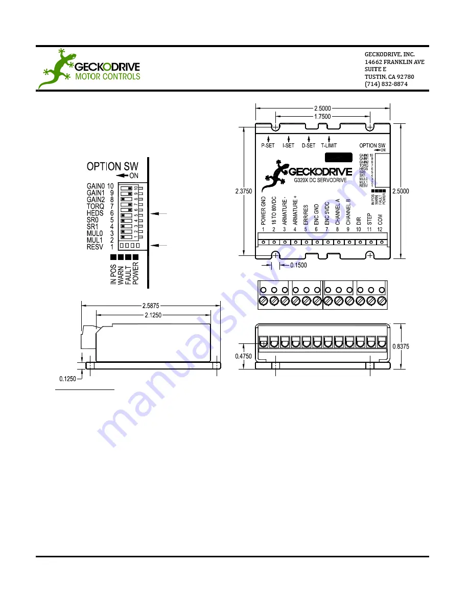
Status LEDs

Option Switches

G320X SERVO DRIVE


REV 10: May 13, 2010 


G320X SPECIFICATIONS 

Power Supply: 


+18VDC to +80VDC 

Quiescent Current: 


30mA 

Motor Current: 


0 to 20 Amps 

Motor Inductance: 


At least 1mH 

Short Circuit Protect:   

22A trip 

Lock Range: 


+/- 256, 512, 1024, or 2048 

Feedback:   


Quadrature TTL Encoder 5V Compatible 

Feedback Resolution:  

X4 Encoder Line Count 

Feedback Voltages: 


<1V for Logic 0 and >4V for Logic 1 

Switching Frequency:   

20kHz 

Current Limit: 


0 to 20 Amps Trimpot Adjustable 

Analog PID: 


Proportional, Derivative, Integral Coefficient Trimpots 

Step Pulse Frequency:  

0 to 500kHz 

Step Pulse “0” Time:   

0.5uS 

Step Pulse “1” Time:   

1.5uS 

Size: 


2.5” x 2.5” x 0.8375” 

Package:   


Blue aluminum anodized cover, black aluminum hard anodized bottom heatsink 

Weight: 


3.6 oz. (100g) 

Encoder Supply: 


+5VDC 50mA maximum 

Pulse Multiplier: 


1, 2, 5, or 10 times input step rate 

Summary of Contents for G320X

Page 1: ...at Finally have a STEP and DIRECTION pulse source available Before going on turn the P I D and LIMIT trimpots to the 11 o clock position The trimpots are single turn so be careful not to over torque...

Page 2: ...256 count following error limit default SW4 OFF and SW5 ON 512 count following error limit SW4 ON and SW5 OFF 1024 count following error limit SW4 OFF and SW5 OFF 2048 count following error limit SW6...

Page 3: ...POWER SUPPLY IMPORTANT Never put a switch on the DC side of the power supply This will damage if not destroy your drive Keep the power supply leads short and use the largest wire gauge that will easil...

Page 4: ...this terminal STEP 7 TUNING THE SERVO Turn on the power supply The FAULT indicator should turn off and the IN POSITION indicator should turn on after 1 second If everything is correct you may hear fa...

Page 5: ...momentary load on the motor while the oscilloscope shows how it responds see oscilloscope traces above If you are using an oscilloscope use channel 1 on TP1 and channel 2 on the DIRECTION input Set t...

Page 6: ...r on reset circuitry in the G320X It will stay in this state indefinitely until it is cleared by applying 5V to this terminal for at least 1 second The voltage on this terminal is 5VDC when the G320X...

Page 7: ...Feedback Resolution X4 Encoder Line Count Feedback Voltages 1V for Logic 0 and 4V for Logic 1 Switching Frequency 20kHz Current Limit 0 to 20 Amps Trimpot Adjustable Analog PID Proportional Derivativ...

Reviews: