12
96263-01.2016-DGbFEIRu
D
GB
F
E
I
Ru
4.3 Pipe connections
4
|
Compressor assembly
ATTENTION Damage possible.
Superheating can damage the valve.
Remove the pipe supports from the valve for soldering.
Only solder using inert gas to inhibit oxidation products (scale).
The discharge gas connection can be moved upwards with an
adapter (accessory). This makes it easier to remove the com-
pressor from a refrigerating system.
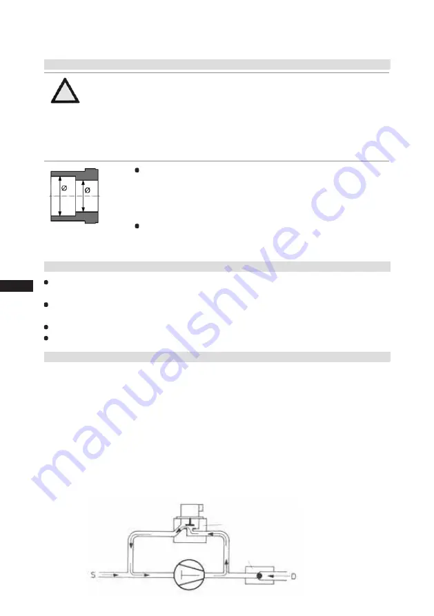
Fig. 15: graduated
internal diameter
Pipe connections on the compressor are available for soldering or
welding (accessories). The
discharge and suction line valves
have
graduated inside diameters so that pipes with standart millimetre and
inch dimensions can be used. The pipe will be immersed more or less
deeply according to dimension.
The connection diameters of the shut-off valves are rated for maximum
compressor output.
The actual required pipe cross section must be
matched to the output. The same applies for non-return valves.
4.4 Pipes
Pipes and system components must be clean and dry inside and free of scale, swarf and layers of
rust and phosphate. Only use air-tight parts.
Lay pipes correctly. Suitable vibration compensators must be provided to prevent pipes being
cracked and broken by severe vibrations.
Ensure a proper oil return.
Keep pressure losses to an absolute minimum.
4.5 Start unloader (external)
A internal start unloader ex factory is not available. Alternatively a start unloader can be installed in
the plant.
Operation:
When the compressor is started, a solenoid valve receives power via a time switch and opens a by-
pass between the discharge- and suction line. At the same time, a non-return valve in the discharge
line closes and prevents a backflow of refrigerant from the condenser (Fig. 16).
The compressor is now short-circuited and delivers from the outflow directly into the intake. The
pressure differential consequently decreases substantially. As a result, the torque on the drive shaft
of the compressor is considerably diminished. The drive motor can now start with a low level of
starting torque. As soon as the motor and the compressor reach their rated speed, the solenoid valve
closes and the non-return valve opens (Fig. 17). The compressor now works under normal load.
Solenoid valve actuated
Non-return valve closed
Fig. 16


