Maintenance
Grease wheel hub bearings
2018-9015-005
09-2016
9.9
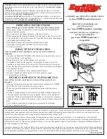
Torque wheel nuts
Before each use or every 10 hours
Note!
It is of prime importance to check the torque of the nuts after the 3 to
5 first trips.
● Ensure wheel nuts are torqued to
375 ft-lb [508 NM];
● To torque wheel nuts, follow the
sequence illustrated.
9.10
Grease wheel hub bearings
Every 200 hours of use
Note!
Use grade 2 - 880 Crown and Chassis grease (or equivalent).
● Using a jack, lift the axle until the tire
no longer touches the ground;
● Unscrew the hub dust cap (1);
● Remove the grease by cleaning the
cap and the bearing;
● Remove the cotter pin (2);
1
3
2
● Check the torque of the wheel hub assembly as follows:
- Torque the castle nut (3) to 190 ft-lb [258 NM] to ensure seating of the
bearing assembly;
- Unscrew the castle nut to the next slot to allow the cotter pin installation.
This step releases pressure on bearings in order to prevent overheating;
- Check the assembly. Make sure there is no gap in the bearing assembly
by moving the tire. Make sure the wheel can be easily rotated by hand.
If checks fail, redo the steps;
● Reinstall the cotter pin (2);
● Cover the bearing with grease. Completely fill the gap with grease between
the bearing and the hub;
● Fill the cap with grease and reinstall it.