


Modifications reserved
Page 51/79
OPM_SGS_USM_M22_M30_2US_V010.doc
User Manual
SG Series 225 & 300 UL S2
7.1.3 From Manual Bypass Q2 (option) to normal function VFI
NOTE !
UPS system has been turned
OFF
following the
“Maintenance shutdown (Load on
Manual Bypass Q2)”
procedure and the
Load
is still powered by
Manual Bypass Q2
(option)
.
The
Load
must be transferred back to the
UPS system
.
Open the front door and make sure that:
•
The
safety screens
are fixed in their position.
•
The
UPS Output Switch Q1
and the
External Battery Switch or Fuses
are open (Pos. O).
•
The
Manual Bypass Switch Q2 (option)
is closed (Pos. I).
•
LED Alarm
is lit.
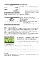
Initial status:
Load supplied from Manual Bypass Q2 (option)
.
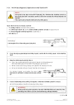
1. If not already supplied (separate Utility Inputs), switch-ON the Utility power to the Rectifier
input.
2. Close the UPS Output Switch Q1 (Pos. I)
.
•
Load
is now supplied parallel through
Automatic Bypass
and
Manual Bypass Q2
.
LED 8 (Automatic Bypass ON)
and
LED 9
(Manual Bypass Q2 ON)
are lit.
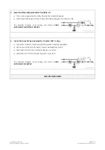
•
Rectifier
starts automatically, blinking
LED 3 (Rectifier ON)
indicates Soft-start.
•
At the end of
Rectifier
Soft-start the
LED 3 (Rectifier ON)
remains lit.
The
Synoptic Diagram
must display the status
“
LOAD
SUPPLIED BY AUTOMATIC BYPASS AND MANUAL BYPASS
Q2
”
.
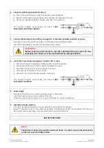
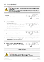
3. Connect the Battery to the UPS by closing (Pos. I) the External Battery Switch or Fuses.
LED 4b
(Charging Battery)
should be lit indicating
battery charge
.
ATTENTION !
Before performing this operation, the
LED 3 (Rectifier ON)
must remain lit, thus
indicating that the DC-Link has reached floating voltage (540Vdc)!
Continue
►


