


GEK-98846A
73
α
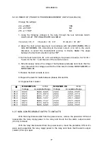
= degrees that V leads I
α
REACTZ1ØG-5IN In=5A
REACTZ1ØG-1IN In=1A
Voltage
Acceptable Range
Voltage
Acceptable Range
+49.0
51.83
49.24 - 54.42
20.73
19.70 - 21.77
+59.0
45.64
43.35 - 47.92
18.25
17.34 - 19.17
+69.0
41.90
39.81 - 44.00
16.76
15.92 - 17.60
+79.0
39.85
37.86 - 41.84
15.94
15.14 - 16.74
+89.0
39.12
37.17 - 41.08
15.65
14.87 - 16.43
+99.0
39.61
37.63 - 41.59
15.84
15.05 - 16.63
+109.0
41.37
39.30 - 43.44
16.55
15.72 - 17.38
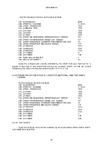
6.2.5.2. REACH OF PHASE TO GROUND MEASUREMENT UNIT Z2 (AG, BG, CG)
Change the settings:
213 - Z3 TRIP:
NO
214 - Z2 TRIP:
YES
215 - Z1 TRIP:
NO
225 - Z2 REACH:
9.00
1. Apply the following voltages to the relay through the rear terminals A2-A3,
A4-A5, A6-A7. THE ANGLES ARE LAGGING!
VA (A2-A3) = 67
0°
VB (A4-A5) = 67
120°
VC (A6-A7) = 67
240°
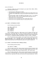
2. Adjust the fault current argument in accordance with table REACTZ2ØG-5IN or
table REACTZ2ØG-1IN, according to the rated current: (it is left to the user's
discretion to select the characteristic point(s) to check).
3. Set the fault current (IA, IB, or IC according to the phase in fault) to 3 A for IN =
5 and 2 A for IN = 1 and the rest of the currents to zero.
4. Reduce the voltage of the phase in fault gradually and check that the relay trips
when the voltage is within the limits listed in tables REACTZ2ØG-5IN or
REACTZ2ØG-1IN.
5. Reduce the fault current to zero.
6. Repeat the tests for faults in phases BG and CG.
Summary of Contents for MLP1000
Page 94: ...GEK 98846A 93 Figure 1 System diagram with MLP CPR and TTI ...
Page 95: ...GEK 98846A 94 Figure 2 Case dimensions and drilling form 1 rack ...
Page 96: ...GEK 98846A 95 Figure 3 1 External Connections MLP1000 ...
Page 97: ...GEK 98846A 96 Figure 3 2 External Connections MLP1000 ...
Page 99: ...GEK 98846A 98 Figure 3 4 External Connections MLP1000 ...
Page 100: ...GEK 98846A 99 Figure 3 5 External Connections MLP2000 ...
Page 101: ...GEK 98846A 100 Figure 3 6 External Connections MLP2000 ...
Page 103: ...GEK 98846A 102 Figure 3 8 External Connections MLP2000 ...
Page 104: ...GEK 98846A 103 Figure 3 9 External Connections MLP3000 ...
Page 105: ...GEK 98846A 104 Figure 3 10 External Connections MLP3000 ...
Page 107: ...GEK 98846A 106 Figure 3 12 External Connections MLP3000 ...
Page 108: ...GEK 98846A 107 Figure 4 Protection Logic ...
Page 109: ...GEK 98846A 108 Figure 5 1 Trip decision diagram ...
Page 110: ...GEK 98846A 109 Figure 5 2 Trip decision diagram ...
Page 111: ...GEK 98846A 110 Figure 5 3 Trip decision diagram ...
Page 112: ...GEK 98846A 111 Figure 5 4 Trip decision diagram ...
Page 113: ...GEK 98846A 112 Figure 6 1 Z1X protection scheme ...
Page 114: ...GEK 98846A 113 Figure6 2 ACCZ2 Protection scheme ...
Page 115: ...GEK 98846A 114 Figure7 LPU function diagram ...
Page 116: ...GEK 98846A 115 Figure 8 1 ROD function logic ...
Page 117: ...GEK 98846A 116 Figure 8 2 ROD function diagram ...
Page 118: ...GEK 98846A 117 Figure 9 1 DD function logic ...
Page 119: ...GEK 98846A 118 Figure 9 2 DD function diagram ...
Page 120: ...GEK 98846A 119 Figure 10 1 FF function logic ...
Page 121: ...GEK 98846A 120 Figure 10 2 FF function diagram ...
Page 122: ...GEK 98846A 121 Figure 11 1 Recloser diagram ...
Page 123: ...GEK 98846A 122 Figure 11 2 Recloser Diagram ...
Page 124: ...GEK 98846A 123 Figure 11 3 Recloser Diagram ...
Page 125: ...GEK 98846A 124 Figure 12 Fault selector ...
Page 126: ...GEK 98846A 125 Figure 13 Menu Tree Diagram ...
Page 127: ...GEK 98846A 126 Figure 14 MLP3000 Settings and data ...
Page 128: ...GEK 98846A 127 Figure 15 Connection scheme for relay tests ...
Page 129: ...GEK 98846A 128 Figure 16 Power swing diagram function ...
Page 130: ...GEK 98846A 129 Figure 17 Mho Reactance characteristics of the MLP ...


