GEK-98846A
49
↑
/
↓
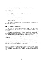
Changes the option. This is equivalent to lateral movement within the circular
menu. When the desired option appears on the screen, use the ENT key to select it.
The use of these keys and others, minus generic keys, (together with concepts
such as circular. logical keys, etc...) will be explained in detail when describing each group.
5.4.2 INFORMATION GROUP
This group provides information related to the MLP. To access this option, press the
INF key when the MLP is in standby. When entering the information menu, the first group
of information elements will be displayed:
EVENT
LOGS
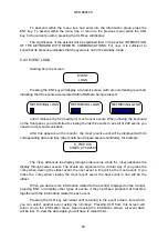
By pressing the
↑
/
↓
keys, the following groups will appear on the screen:
EVENT LOGS
CURRENT LOGS
POWER LOGS
MLP STATUS
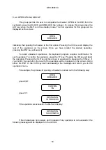
pressing
↑
displays:
CURRENT
LOGS
pressing
↑
displays again:
POWER
LOGS
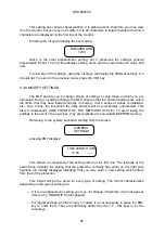
pressing
↑
displays:
MLP STATUS
and pressing
↑
displays the first menu (in a circular mode):
EVENT
LOGS
Summary of Contents for MLP1000
Page 94: ...GEK 98846A 93 Figure 1 System diagram with MLP CPR and TTI ...
Page 95: ...GEK 98846A 94 Figure 2 Case dimensions and drilling form 1 rack ...
Page 96: ...GEK 98846A 95 Figure 3 1 External Connections MLP1000 ...
Page 97: ...GEK 98846A 96 Figure 3 2 External Connections MLP1000 ...
Page 99: ...GEK 98846A 98 Figure 3 4 External Connections MLP1000 ...
Page 100: ...GEK 98846A 99 Figure 3 5 External Connections MLP2000 ...
Page 101: ...GEK 98846A 100 Figure 3 6 External Connections MLP2000 ...
Page 103: ...GEK 98846A 102 Figure 3 8 External Connections MLP2000 ...
Page 104: ...GEK 98846A 103 Figure 3 9 External Connections MLP3000 ...
Page 105: ...GEK 98846A 104 Figure 3 10 External Connections MLP3000 ...
Page 107: ...GEK 98846A 106 Figure 3 12 External Connections MLP3000 ...
Page 108: ...GEK 98846A 107 Figure 4 Protection Logic ...
Page 109: ...GEK 98846A 108 Figure 5 1 Trip decision diagram ...
Page 110: ...GEK 98846A 109 Figure 5 2 Trip decision diagram ...
Page 111: ...GEK 98846A 110 Figure 5 3 Trip decision diagram ...
Page 112: ...GEK 98846A 111 Figure 5 4 Trip decision diagram ...
Page 113: ...GEK 98846A 112 Figure 6 1 Z1X protection scheme ...
Page 114: ...GEK 98846A 113 Figure6 2 ACCZ2 Protection scheme ...
Page 115: ...GEK 98846A 114 Figure7 LPU function diagram ...
Page 116: ...GEK 98846A 115 Figure 8 1 ROD function logic ...
Page 117: ...GEK 98846A 116 Figure 8 2 ROD function diagram ...
Page 118: ...GEK 98846A 117 Figure 9 1 DD function logic ...
Page 119: ...GEK 98846A 118 Figure 9 2 DD function diagram ...
Page 120: ...GEK 98846A 119 Figure 10 1 FF function logic ...
Page 121: ...GEK 98846A 120 Figure 10 2 FF function diagram ...
Page 122: ...GEK 98846A 121 Figure 11 1 Recloser diagram ...
Page 123: ...GEK 98846A 122 Figure 11 2 Recloser Diagram ...
Page 124: ...GEK 98846A 123 Figure 11 3 Recloser Diagram ...
Page 125: ...GEK 98846A 124 Figure 12 Fault selector ...
Page 126: ...GEK 98846A 125 Figure 13 Menu Tree Diagram ...
Page 127: ...GEK 98846A 126 Figure 14 MLP3000 Settings and data ...
Page 128: ...GEK 98846A 127 Figure 15 Connection scheme for relay tests ...
Page 129: ...GEK 98846A 128 Figure 16 Power swing diagram function ...
Page 130: ...GEK 98846A 129 Figure 17 Mho Reactance characteristics of the MLP ...


