background image

g


Product Data Sheet – rev 4.2 
July 4th 2003  
Page 8 


LightSpeed

16


With Xtream 

CT Scanner System 

GE Medical Systems-America 
Milwaukee, USA  - Fax: 1 414 544 3384 
GE Medical Systems-Asia: 
Tokyo, Japan - Fax: 81 425 85 5490 
Hong Kong - Fax: 852 2559 3588 
GE Medical Systems-Europe 

Reconstruction Matrix: 512  

Scan Mode

Slice

Thickness

Recon

 Slice Thicknesses

16 row

0.625

16i - 0.625mm

8i - 1.25mm

4i - 2.5mm
2i - 5.0mm

16row

1.25

16i - 1.25mm

8i - 2.5mm
4i - 5.0mm

2i - 10mm

8 row

1.25

8i - 1.25mm

4i - 2.5mm
2i - 5.0mm

1i - 10mm

8row

2.5

8i - 2.5mm
4i - 5.0mm

2i - 10mm

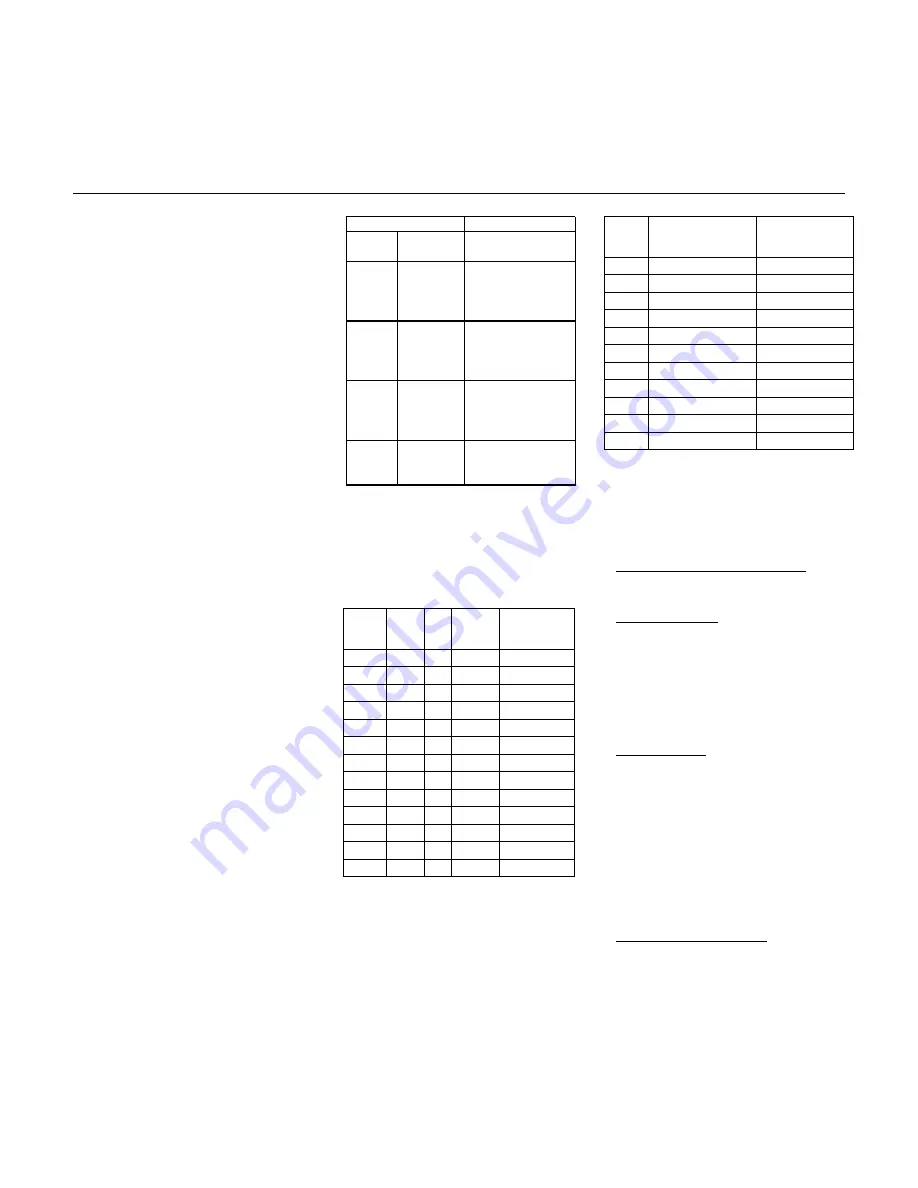
Prospective Perscription


mA 

# Scans 

(Clusters)  

Acquisition 

Time


440 15-45 

(3-11) 0:41-2:49 

400 25-55 

(5-13) 1:13-3:21 

340 35-75 

(7-18) 1:45-4:41 

320 45-85 

(9-20) 2:17-5:13 

300 50-95 

(10-22)  2:33-5:45 

280 60-110 

(12-25)  3:05-6:33 

260 75-125 

(13-28)  3:21-7:21 

240 85-145 

(14-31)  3:37-8:09 

220 100-170 

(16-34) 

4:09-8:57 

200 115-185 

(18-38)  4:41-10:01 

180 135-250 

(22-43)  5:45-11:21 

Display Matrix: 1024. 

Display FOV: Freely variable center/off-center, 
prospective/retrospective target selection. 

CT Number Scale:  -1024 to 3071 HU 

Axial Image Reconstruction: 

• 

 Reconstruction time as fast as 6 images 
per second.  

• 

Typical 0.167 sec. image-to-image recon in 
16 slice recon mode. 

• 

Maximum image-to-image cycle time is 
± 10% for prospective and retrospective 
image-to-image display. This applies for 
512 matrix; any display FOV; in 
AutoView (all layouts); with concurrent 
filming and image archival for all scan 
modes. 

Axial Scan Image Quality 

Axial Scan Protocols 

For details of scan technique parameters, 
please refer to the technical reference 
manual. 

• 

Iterative bone processing increases time by 
250 milliseconds. 

All protocols assume 120 kVp scans under 
typical clinical conditions. 

High Contrast Spatial Resolution: 

Prospective Multiple Reconstruction 
(PMR): Up to 3 sets of reconstructions can 
be pre-programmed as part of the scan 
protocol prior to acquisition.  The operator 
can select different reconstruction 
algorithms and display fields of view for 
each reconstruction.  This frees the 
operator from sitting at the console and 
directly contributes to increased 
productivity. 

Standard Scans: 

On GE Performance phantom: 


Scan 
Time 


ISD mA


Scans

Acquisition 

Time


1 sec.  1 sec. 440

18-45 0:35-1:27 

1 1 400

24-55 0:47-1:49 

1 1 360

32-68 1:03-2:15 

1 1 340

37-76 1:13-2:31 

1 1 320

43-86 1:25-2:49 

1 1 300

50-97 1:37-3:11 

1 1 280 58-110 1:45-3:37 
1 1 260 66-122 1:55-3:59 
1 1 240 74-135 2:07-4:21 
1 1 220 84-152 2:21-4:49 
1 1 200 94-168 2:37-5:21 
2 1 200

37-77 1:13-2:33 

2 1 180

42-86 1:23-2:51 

Standard Algorithm 

• 

0.584 mm limiting resolution 

• 

4.0 lp/cm @ 50% MTF 

• 

6.5 lp/cm @ 10% MTF 

• 

8.5 lp/cm @ 0% MTF 

The operator has the option to reconstruct 
the original raw data set at any of the 
defined nominal slice thicknesses. 

Hi-Res Algorithm 

• 

0.324 mm limiting resolution 

Reconstructions can be prescribed down 
to 1/16 the original acquisition image 
thickness for images acquired in the 1i 
scan mode, down to 1/8 the original 
thickness for 2i mode, and down to 1/4 the 
original thickness for 4i mode. 

• 

8.5 lp/cm @ 50% MTF 

• 

13.0 lp/cm @ 10% MTF 

• 

15.4 lp/cm @ 0% MTF 

Similarly, additional reconstruction 
supports partial-volume artifact reduction 
by reconstructing images with 4, 8, or 16 
times the acquisition image thickness. 

Line pair values decrease with larger focal 
spot (by 5% with Standard and by 7% with 
Hi-Res); limiting resolution is unaffected. 


• 

Cluster Scans (All cluster protocols assume 
9-second clusters of five slices, 1-second 
scans with 1-second interscan delays and 7 
seconds between clusters). 

Low-Contrast Detectability 

These reconstruction features effectively 
facilitate later, more detailed image 
analysis without additional patient scans 
and subsequent dose and image 
registration concerns. 

On 8 inch (20 cm) CATPHAN phantom: 

5mm @ .3% at 13.3 mGy  
3mm @ .3% at 37.2 mGy  

The following table illustrates the 
retrospective reconstruction image 
thicknesses available for each acquisition 
thickness and mode: 

* Option 

Summary of Contents for LightSpeed 16

Page 1: ...o provide an optimized workflow solution from acquisition to final report Lowest dose acquisition using SmartmA TM an automatic modulation technique and DLP display that tells the operator the dose before the scan starts HyperPlane TM reconstruction algorithm tackles the inherent issues with fast high pitch helical scanning by reducing helical artifacts and dose and optimizing the slice profile Cr...

Page 2: ... may allow you to reduce contrast media perform better thin slice CT angiography exams use thinner slices for most exams and perform longer helical exams without tube cooling delays Remote Gantry Tilt from the Operator s Console to increase exam speed including built in safety features to prevent accidental contact of the gantry with the patient CTDIw DLP Dose Length Product and Dose Efficiency di...

Page 3: ...exam to the patient All console components monitors keyboard mouse and BrightBox are free standing and can be easily moved on the front work surface Large 1024 color display Patient demographics and exam protocols can be preprogrammed in advance of patient arrival through the Schedule Patient feature Leading edge real time image processing MPR MPVR Volume Viewer All surfaces made of high impact re...

Page 4: ...ontinue with additional helical scans or a set of axial scans Helical 8 SLICE HELICAL MODES Table Speed mm rotation Slice Thick ness mm Pitch 0 625 1 0 875 1 1 35 1 1 675 1 1 25 6 25 8 75 13 5 16 75 2 5 6 25 12 5 8 75 17 5 13 5 27 0 16 75 33 5 3 75 6 25 12 5 8 75 17 5 13 5 27 0 16 75 33 5 5 6 25 12 5 8 75 17 5 13 5 27 0 16 75 33 5 7 5 6 25 12 5 8 75 17 5 13 5 27 0 16 75 33 5 10 6 25 12 5 8 75 17 5...

Page 5: ...16 slice recon mode Ten user defined regions Each region has one default protocol displayed with the anatomical selector for very fast access to most commonly used protocols Scan Speeds Full 360 rotational scans in 0 5 0 6 0 7 0 8 0 9 1 0 seconds Maximum image to image cycle time is 10 for prospective and retrospective image to image display This applies for 512 matrix any display FOV in AutoView ...

Page 6: ...413 Prospective Recon Operator may initiate full recons at any table location in increments of 1 10 the image thickness image thickness remains constant 0 5mm Retrospective Recon Operator may initiate full recons at any table location in 0 1 mm increments image thickness remains constant Retrospective Image Decomposition The operator has the option to retrospectively decompose the original raw dat...

Page 7: ...e increment Gantry display in 0 5 mm increments On 8 inch 20 cm CATPHAN phantom 5 mm 3 at 13 3 mGy 3 mm 3 at 37 2 mGy For each rotation of the gantry the LightSpeed 16 collects 16 rows of scan data There are five reconstruction modes available for creating images from the multi slice scan data 1i 2i 4i 8i and 16i By using 1i 2i 4i and 8i reconstruction modes scan data can be combined prior to imag...

Page 8: ...r to acquisition The operator can select different reconstruction algorithms and display fields of view for each reconstruction This frees the operator from sitting at the console and directly contributes to increased productivity Standard Scans On GE Performance phantom Scan Time ISD mA Scans Acquisition Time 1 sec 1 sec 440 18 45 0 35 1 27 1 1 400 24 55 0 47 1 49 1 1 360 32 68 1 03 2 15 1 1 340 ...

Page 9: ...aker microphone and volume controls CTDIvol expressed in mGy 100 mAs Three button mouse with mouse pad The ImageWorks desktop also provides a gateway for DICOM 3 0 image transactions either through a local area network or via DICOM formatted MOD media Head 18 4 mGy 100 mAs Body 9 3 mGy 100 mAs BrightBox trackball assembly Two wide work surfaces Scout Scans All these devices are free standing and c...

Page 10: ...removed from the prescription Scan recon control uses only 2 screens to set up first scan New Patient and Protocol View Edit Dose Computation Display CTDIvol CTDI volume DLP Dose Length Product and Dose Efficiency computation and display during scan prescription provides patient dose information to the operator Protocol View Edit A single full screen View Edit table allows fast and easy examinatio...

Page 11: ...lows full use of the image display monitor for AutoView and image review processing without interruption during AutoFilm Gray Scale Enhancement An AutoFilm Composer provides a simple programming interface for automated filming set up ProView visualization algorithms are available to enhance anatomical structures without additional reconstruction time Batch Filming is accomplished through a single ...

Page 12: ...is is the ultimate tool to assess and quantify vascular structures including stenosis analysis stent planning procedures post stenting or vascular surgery follow up protocol driven tools to perform quick flexible and accurate quantitative analysis of vascular anatomy provides maximum minimum and mean intraluminal diameter measurements provides cross sectional areas of true orthogonal sections of t...

Page 13: ... sec and 40 mm sec System Components Horizontal Range 170 cm Horizontal Scannable Range 170 cm metal free axial and 160 cm metal free helical Scout Gantry Image transfer time using either AdvantageNet or DICOM 3 0 protocols is approximately 0 1 second per 512 image on a 100baseT Network Horizontal Speed Up to 100 mm sec Advanced slip ring design continuously rotates generator tube detector and dat...

Page 14: ... disk drive Average time to replace tube 10 hours High Performance Drive 2GB DDR266 Dual Channel Memory with a throughput of 4 2GB sec 36 GB 3 5 inch form factor High Voltage Generation UltraSCSI interface Image Processor High frequency on board generator Continuous operation during scan Standard MOD drive Nvidia Quadro4 980XGL AGP 8X graphics with 128MB Memory Magnetic Optical Disk Drive 53 2 kW ...

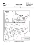
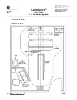
Page 15: ...time and receive pull query and storage commitment push Siting Requirements Minimum Suite Size AdvantageNet GenesisNet point to point send receive and pull query no broadcast Overall Suite Compatible UPS options are available if desired 15 5 feet 4 74 m wide x 19 5 feet 5 96 m deep x 9 feet 2 75 m high InSite point to point Cooling Requirements TCP IP for system administration Recommended Suite Si...

Page 16: ...ight 1 887 74 1 Table Width 610 24 Length 5 050 199 Height 1 120 44 Power Distribution Unit Width 762 30 Depth 585 23 Height 1 270 50 Operator Console Width 1 238 48 7 Depth 1 288 50 7 Height 1 257 49 5 Warranty The published Company warranty in effect on the date of shipment shall apply The Company reserves the right to make changes All specifications are subject to change Regulatory Compliance T...

Page 17: ...4th 2003 Page 17 LightSpeed16 With Xtream CT Scanner System GE Medical Systems America Milwaukee USA Fax 1 414 544 3384 GE Medical Systems Asia Tokyo Japan Fax 81 425 85 5490 Hong Kong Fax 852 2559 3588 GE Medical Systems Europe Option ...

Page 18: ...htSpeed16 With Xtream CT Scanner System GE Medical Systems America Milwaukee USA Fax 1 414 544 3384 GE Medical Systems Asia Tokyo Japan Fax 81 425 85 5490 Hong Kong Fax 852 2559 3588 GE Medical Systems Europe Minimum Room Layout Typical Room Layout Option ...

Reviews: