Innova 2000 Cardiovascular Imaging System
GE Medical Systems
Pre–Installation Manual
REV 5
pim 2337741–100
46
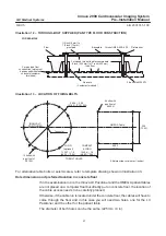
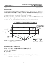
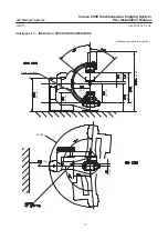
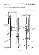
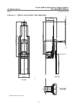
Illustration 14 – HOLE LOCATIONS IN CONCRETE FLOOR
ÉÉÉ
ÉÉÉ
ÉÉÉ
ÉÉÉ
ÉÉÉ
ÉÉÉ
ÉÉÉ
diameter 225 mm
or 9 inches
OMEGA IV
Cables
entrance
195
(7.677)
Isocenter
diameter 225 mm
or 9 inches
254
off centered in the
longitudinal axis
All dimensions are in mm
(inches)
INNOVA LC POSITIONER
OMEGA IV
Note : If both hole are the same diameter, it must be 1641 mm (64.6 in) or 1537 mm (60.5 in).
COMPACT or LONG
1641 mm
3 mm
(64.6
0.12)
COMPACT or LONG
1573 mm
3 mm
(61.93
0.12)
No cable entry
in this area
(10.0)
COMPACT or LONG
1700 mm
3 mm
(66.93
0.12)
LONG (optional)
1456 mm
3 mm
(57.32
0.12)
LONG (optional)
1537 mm
3 mm
(60.5
0.12)
LONG (optional)
1583 mm
3 mm
(62.32
0.12)
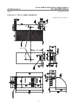
Due to the plastic bushing used in the USA to protect cables from the sharp
edges of conduits it is necessary to place the cable conduit inside the table
cable access opening but the height of the outcoming conduit plus bushing
is limited to 1/2 in (12 mm).
Water Pipe Requirements
An Innova LC System uses a MAXIRAY 150 with a recirculating chiller.
Two water pipes are supplied to allow water circulation between Innova LC Positioner and
chiller.
In some countries, it is forbidden to run electrical cables and water pipes in the same conduit.
In this case, two separate conduits are required. But then a problem arises at the level of the
Innova LC Positioner entrance.
Depending on the method used, one of the two options shown hereafter (Illustration 15) must
be used.
Seismic areas
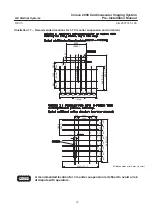
In Seismic areas all cabinets must be anchored to the floor. See Chapter 2 for referential documents.
Every sub–system is delivered on site with its proper seismic kit.
Anti–seismic means be installed before opening the system for normal use.
CAUTION


