Innova 2000 Cardiovascular Imaging System
GE Medical Systems
Pre–Installation Manual
REV 5
pim 2337741–100
117
5
POWER & GROUNDING RECOMMENDATION
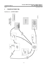
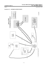
Impedance of the ground wire to earth should be lower than 2 ohms (refer to direction 46–019668
for method of measurement).
This cable should be at minimum a 25 square mm sized wire (AWG2).
The power supply cable of the PDB power unit and of the generator shall come from a subpanel,
as long as the wires are sized to ensure proper voltage drop.
These cables must not be used to supply other systems and be in conformity with local regulation
(UL, CSA, IEC, and of Size: AWG2 or AWG4).
Max line Impedance for PDB cable and generator cable
V
380
400
420
440
460
480
0.09
0.096
0.102
0.108
0.114
0.12
Note:
These cables are not furnished by GEMS; they are provided by the installer.
These cables must be kept separated as much as possible from room system cables.
Power and ground must come from the same distribution panel. They must run near one another.
The shield of any shielded cable coming from the distribution cannot replace the ground wire.
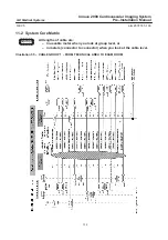
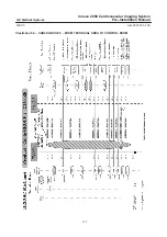
Reference: For specific Vascular system grounding maps and connection details, refer to the MisMap
and mis chart listed in Section 6.
6
MIS (MASTER INTERCONNECT SYSTEM)
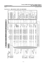
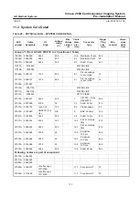
Advantx LC+ system interconnect cables are described in MIS (Master Interconnect System)
documents. These documents specify all interconnections between components within the system.
Reference: For specific Vascular system interconnect maps and connection details, refer to the
following:
Document 2337742–100, INNOVA 2000 MIS Map
Document 2337743–100, INNOVA 2000 MIS Charts.
General Guidelines
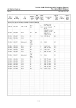
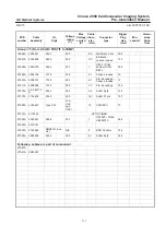
Innova 2000 introduce a new system interconnect with a star distribution for all cables from the
technical area. The cables are shipped on spools to create cable groups. Cable group 1 for Exam
room and cable group 2 for control room. The cable group shall be put in place during the same action,
keeping if necessary the plastic sleeve. The cables are routed in the same duct.
The HV cables could be pulled separately.
Minimize cable length between the power input panel and the VAMP and Atlas Cabinet. These line
cables shall be routed in separate duct.

