


GEH-1791
ELECTRICAL TESTS
Before the following electrical tests are made, the relay should be in its case,
preferably mounted in its permanent location.
A typical elementary diagram of external connections is shown in Figure 12.
The 11 b11
contact of 52 in series with only one coil circuit serves to reset the disk and
contacts promptly after the circuit breaker closes, so that the normal delay is
available as soon as possible in case the breaker trips again.
Additional relays
(undervoltage or reclosing) may be considered desirable for prevention of unlimited
reclosures in case of one wire broken and grounded or crossed with another phase.
The relay closing angle should be set as required for its permanent location, which
would normally be 200.
Connect the relay as shown in Figure 11 and check that the
relay picks up at the proper phase angle
:
30.
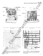
If a phase angle meter or a phase shifter is not available, it is possible to adjust
the relay to approximately the closing angle desired by means of the connections and
curve shown in Figure 14. In this test, rated voltage is held on one circuit (studs
7 -8) and a reduced voltage is applied to the other circuit (studs 5-6).
The voltage
connected to studs 5-6 is adjusted until the synchronizing check unit just closes
its contact.
The difference between the two voltages should agree approximately
with the voltage given on the curve shown in Figure 14 for the phase angle used
(i. e. 24 volts for 200 closing).
When using connections shown in either Figure 11 or Figure 13, check the operating
time at 0 displacement with 115 volts on each coil, using the time dial setting of
the permanent location. (See Figure 8 for nominal time delay values. )
PERIODIC CHECKS AND ROUTINE MAINTENANCE
In view of the vital role of protective relays in the operation of a power system,
it is important that a periodic test program be followed. It is recognized that the
interval between periodic checks will vary depending upon environment, type of relay
and the u
s
er
'
s experience with periodic testing.
Until the user has accumulated
enough experience to select the test interval best suited to his individual
requirements, it is suggested that the points listed below be checked at an interval
of from one to two years.
MECHANICAL
The mechanical checks described under the section on
ACCEPTANCE TESTS
should be
repeated.
ELECTRICAL
Using connections in Figure 11,
1.
Check that the maximum closing angle for pickup of the synchronizing check unit
agrees approximately with the value shown on the curve in Figure 7.
8
www
. ElectricalPartManuals
. com