


SYNCHRONISM-CHECK RELAYS
TYPE
INTRODUCTION
The Type IJS relays are of the induction-disk
construction and are intended for use as synchro
nism-check relays.
These relays have two shaded-pole U-magnet
driving-elements acting on opposite sides of a
single rotating disk.
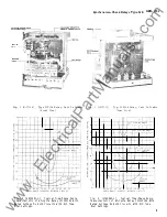
(See Fig. 2 ) One of these,
the operating element, drives the disk in the contact
closing direction, and the other the restraining
element, drives the disk in the opposite direction.
The disk shaft if restrained by a spiral spring,
the purpose being to hold the contacts open when the
relay is de-energized. The motion of the disk is
retarded by permanent magnets (drag magnets)
acting on the disk to give a time delay.
The Type IJS5 1A relay has a seal-in unit
mounted to the left of the disk shaft, which operates
when the main contacts close.
The Type IJS52A relay does not have a seal-in
unit and is used primarily as an auxiliary to the
Type GES Synchronizing relay as described below.
APPLICATION
The Type IJS relay is applicable as a synchro
nism-check relay to permit closure of a circuit
breaker only when the frequency difference is
negligible or is zero due to the two sources which
energize it being interconnected elsewhere.
The IJS51A should be used where a target-seal
in unit is required; otherwise use the IJS52A.
In
such an application the voltages may be
considerably out of phase due to load transfer around
the loop which is open at the breaker controlled
by the relay. Forms of the relay are available with
a rated calibration range up to 60 degrees; but for
settings over 20 degrees consideration should be
given to t�1e resulting generator stresses at the
instant of closure through existing system im
pedances, as in any other situation involving out
of-phase closure.
On systems where the two sides of a given
breaker may or may not be interconnected else
where at any given moment when paralleling is
desired, the GES or GXS is used for synchronizing
when a finite frequency difference exists; and the
IJS is used at the same location for synchronism
IJS
check when the frequency differenc e is negligible
or zero due to the existance of an interconnection
elsewhere.
In
this application, the IJS contacts are
connected in parallel with those of the GES or
GXS.
The IJS is not adaptable to applications in
volving continuous loading of the contact circuit,
since contact welding may result even with contact
loadings that are low in relation to the interrupting
capacity of the contacts.
The control should be
designed to energize the IJS coils when synchronism
is to be checked; and to permit the IJS contacts
to be the last to complete a closing c ircuit which
is promptly bypassed or interrupted.
Cross feed from the energized side to the de
energized side is very low, because the operating
principle of the relay requires the two windings
on the operating magnet to be additive while those
on the restraining magnet are subtractive, and,
therefore, the coupling from the bus side to the
line side coil on the operating magnet is practically
cancelled by the reverse polarity of the corres
ponding coupling between the coil on the restraining
magnet .
OPERATING CHARACTERISTICS
The operating coils, mounted on the left-hand
side, produce a torque tending to close the relay
contacts. This torque is proportional to the vector
sum of the voltages whose phase positions are being
compared.
The torque produced by the restraint
coils is proportional to the vector difference of
the voltages.
The operating torque is maximum
when the systems are in synchronism ami is zero
when they are in phase opposition; the reverse
is true of the restraining torque.
The closing angle of the relay is defined as
the maximum phase displacement of the two voltages
at which the relay will close its contacts when
the voltages are at rated value. The 20-degree
closing angle is considered standard; however,
other settings may be made as indicated by the
voltage-phase angle characteristics shown in Fig. 1.
These instructions do not purport to cover all details or variations in equipment nor to p rovide for
every possible contingency to be met in connection with installation, operation or maintenance.
Should
further information be desired or should particular problems arise which are not covered sufficiently for
the purchaser's purposes, the matter should be referred to the General Electric Company.
To the extent required the products described herein meet applicable ANSI, IEEE and NEMA standards;
but no such assur ance is given with respect to local codes and ordinances because they vary greatly.
3
www
. ElectricalPartManuals
. com