


GEH - 1791 Synchronism-Check Relays Type IJS
The time delay characteristics of the Type
IJS relay are obtained primarily by the time-dial
setting.
The time dial controls the distance the
contacts must travel before closure and, hence,
controls the time delay.
At No. 1 0 time-dial
setting the travel is maximum, whereas, at No. 0
the
contacts are just closed.
A certain amount
of adjustment may be made by changing the position
of the drag magnet on its shelf. Moving it toward
the disk shaft decreases the time delay while moving
it away from the disk shaft increases the time
delay.
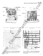
Typical time vs. phase-angle curves are shown
in Figs. 4 and 5 for 60-cycle relays and in Fig.
6 for 2 5-cycle relays.
The model 12IJS51A1
relay has the standard closing angle setting of 20
degrees and has its drag magnet adjusted to provide
20 seconds time delay from No. 10 time-dial
setting for voltages in phase. The closing angle
on this relay can be adjusted to angles greater
than 20 degrees but with a corresponding decrease
in time delay as shown in Fig. 4.
The approximate reset time of the 12IJS51A1A
relay with both coils deemergi zed is 100 seconds at
the #10 TDS.
The approximate reset time with
one coil circuit energized varies from 3 seconds
on the 20 degree setting to 6 seconds on the 6,0
degree setting at the #10 TDS.
The Model 12IJS5 1A3 and 12IJS52A 7A relays,
which are designed for use where the closing angle
greater than 20 degrees is required, provides 20
seconds delay at the 40 degree closing-angle setting,
as shown in Fig.
5.
It
may be adjusted
to other
closing angles between 20 and 60 degrees with
corresponding changes in time delay as shown
in Fig. 5.
The approximate reset times of the 12IJS5 1A3A
and 12IJS52A
7
A relays is 130 seconds at the #1 0
TDS.
The approximate reset time with one coil
energized varies from 13 seconds on the 20 degree
setting to 20 seconds on the 60 degree setting
at the #10 TDS.
The 2 5-cycle Type IJS relay has operating
characteristics as shown in Fig. 6 .
Fig.
7
gives the operating· time in seconds
for various time-dial settings with zero phase
displacement and with rated voltage at 60 cycles
on both circuits. Curves for 2 5 cycles are similar,
except that the operating time from the No. 1 0
time-dial setting i s 32 seconds instead of 20 seconds.
ANGLE
�
T WH I CH OIITACTS
CLOSE WITH RATE VOL
011 BOTH
\
CIRCUITS
Fig. 1 (0165A7535-0)
Typ i cal Voltage -Phase An gle Characte r i stic of 115 Volt 50/60 Cycl e
IJS
R e lay for var i ous
Clos i n g A n g le Adjust me n t s w i th R ated Voltage Main ta i n e d on One Circuit.
4
www
. ElectricalPartManuals
. com