


GEH - 1 79 1 Synchronism-Check Relays Type LJ S
CON�·i ECTI G P LU G
M A I N B R U S H
C O N N E CT I N G BLOCK
A U X I L I !\ R Y B f1 U S H
"
N O T E
A F T E' R E N G M
l N G A U X I L.IA R Y
B R U S H , C O N N ECT I N G PLUG
TR AVEl.S 1 /4
I
N
C
H
B E F O R E
E N G A G I N G
T H E M A I N B R US H O N
T H E TE R M I
N A
L SLOCk.
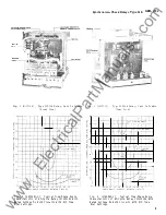
F�c .
1 .
C I 'DSS Sr'Ct.ion o �· Drawout Cas e
f�h:J\·: l :1r: Pos i.t i:Jn CJ · ' k.Lx i l i.ox:· Brush An d Shorting Bar
ELECTRICAL
Using connections in Fig. 10
1. Check that the maximum closing angle for
pick-up of the synchronizing check unit agrees
approximately with the value shown on the curve
in l''ig. 11.
2. Check the closing time with the potentiometer
set to provide 1 1 5 volts on both circuits . The
time should agree with values given in Fig.
7
plus or minus 10 percent.
SERVICING
U
recalibration of the relay i s necessary, the
following should be considered when making adjust
ments.
MECHANICAL ADJUSTMENTS
1. The moving contact should just touch the second
ary contact when the time dial is set at the
zero position.
If
readjustment is necessary,
loosen the two clamping screws which fasten
the stop arm to the shaft and change the
positiin of the stop arm relative to the moving
contact until the contacts just touch with the
time dial set at zero.
A fine adjustment
can be obtained by moving the stationary contact
brush in or out by means of its adjusting screw.
However, in the final adj ustment, the contact
brush must be positioned so that there is 1/64"
to 1/32" wipe with the contact fully closed.
Be sure that the screws are securely tightened
after adjustment is made.
10
2.
The stop arm leaf spring should deflect at
least 1/64" when synchronism-check unit is
de-energized.
3 . The disc and shaft assembly should have a
vertical end play of 1/16" to 1/32" and both
bearing screws should be tight.
The disc
should be approximately centered between the
poles of the U- magnet and drag magnet.
ELECTRICAL ADJUSTMENTS
Closing Angle Adjustment
Connect the relay as shown in Fig. 10. To make
an accurate adjustment of the closing angle, a phase
shifter and phase angle meter are required along
with a means for voltage control.
Two adjustments are necessary for obtaining a
desired closing angle. The right-hand adjustable
resistor at the top of the frame per mits equalizing
the closing angle. That is, the closing angle will
be the same whether one voltage is leading or lagging
the other voltage.
The left-hand adjusting resistor is for obtaining
the correct closing-angle setting. Simultaneously,
adjustments of the two resistors are necessary.
Using connectio:1s shown in Fig. 10 set V 1 at
1 1 5 volts.
If
a 20 degree closing angle is desired,
set v2 at 115 volts, leading
by 20 degrees.
Adjust the left-hand resistor
the contacts just
close. Now with 115 volts on both circuits, determine
the angle at which the contact closes with V2
lagging V1 .
If
the two angles are unequal, equalize
them at 20 degrees by adjusting the right-hand
resistor.
Then check the c losing angle with V2
leading V 1, and readjust, if necessary. Continue
this procedure until the relay contacts just close
for V1 leading or lagging V2 by 20 degrees. Use the
same procedure for other closing-angle settings.
U
it is necessary to adjust the time character
istics, impose the chosen conditions on the relay,
using connections shown in Fig. 10 and adjust the
time dial and, if necessary, the drag magnet until
the correct operating time is obtained.
RENEWAL PARTS
It is recommended that sufficient quantities of
renewal parts be carried in stock to enable the
prompt replacement of any that are worn, broken,
or damaged.
When ordering renewal parts, address the
nearest Sales Office of the General Electric Company,
specify quantity required, name of the part wanted
and give complete nameplate data.
U
possible,
give the General Electric requisition number on
which the relay was furnished.
www
. ElectricalPartManuals
. com