GE Homespring Operation Manual Download Page 44

44

4

Open a nearby cold water high demand tap, then open 

the outlet valve. This will prevent antifreeze from spreading 

throughout the piping system. Run the tap for 30 minutes. 

Open all other cold water taps in the home and flush 

separately for 1 minute each.
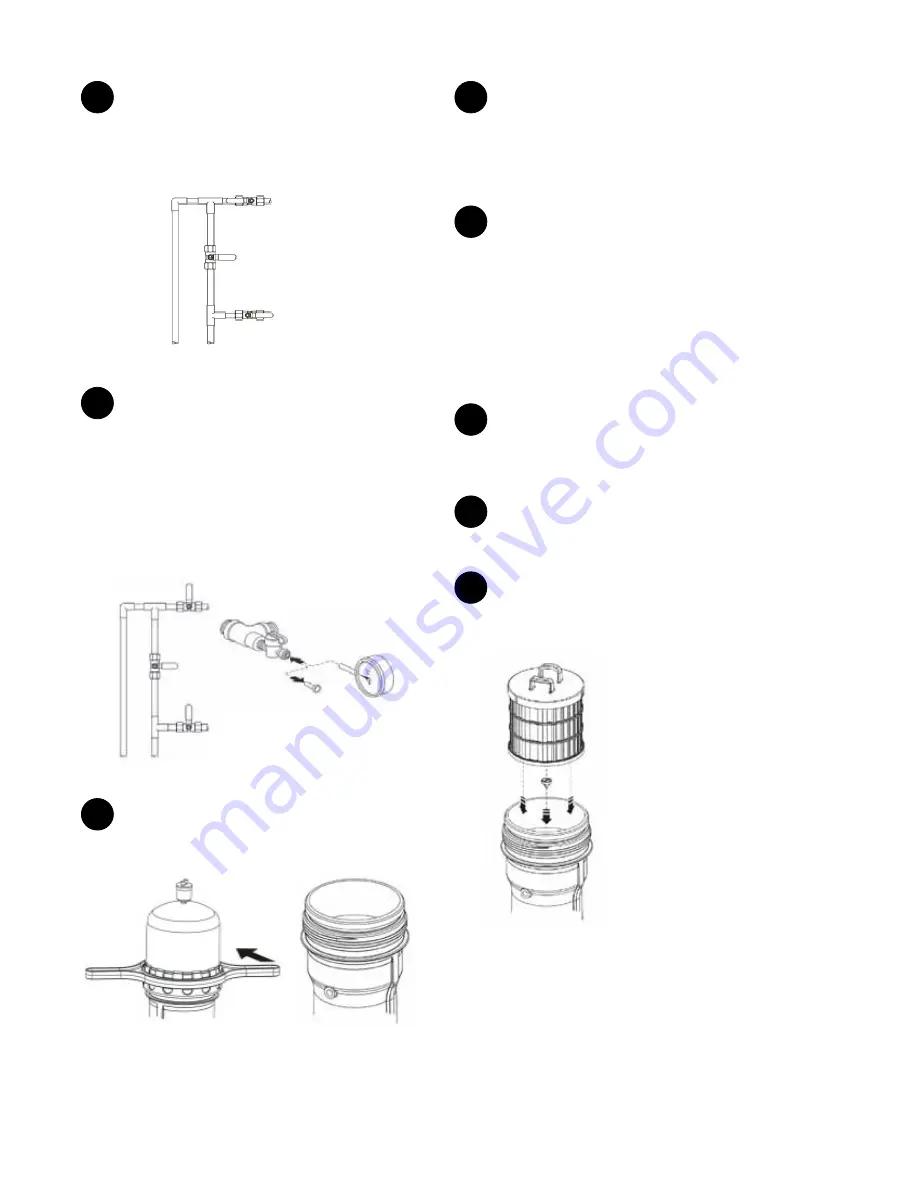
Inlet Valve

Bypass Valve

Outlet Valve

Figure 79 

5

Close the inlet valve and outlet valve. Partially drain the 

system using the manual flush function for 1 minute to 

depressurize the system. Refer to the Controller Functions 

section on how to perform a manual flush sequence. Remove 

the plug from the mini ball valve on the inlet fitting assembly 

by depressing the lock ring and pulling on the plug. Slowly 

open the mini ball valve to ensure there is no pressure in the 

system. Water will flow out, but should not spray. Close the 

mini ball valve immediately. If there is spray, repeat the 

manual flush sequence. Replace the plug in the mini ball valve.

figure 80 

6

Remove system cap. If a stainless steel prefilter was 

stored in the prefilter cavity over the winter remove, wash and 

set aside.

Open

figure 81 

7

Be sure the water level in the system is 2" above the 

bottom of the prefilter cavity. Add more water by slowly 

opening the inlet valve if necessary. Add 2 cups (500 ml) of 

unscented household chlorine bleach (Clorox) (5 - 6% chlorine) 

or 1 cup (250 ml) chlorine bleach (12% chlorine), maximum 3 

months old, to the system.

8

Allow the system to soak for 15 minutes. With the 

system cap tightened, drain the system using the controller. 

Open the inlet valve and allow system to pressurize.

NOTE: 

If the winterization spring start up is combined with the 

annual maintenance cleaning procedure, the System must soak 
for 60 minutes. If the System is on ground or well water, the 
chlorine must be substituted with Homespring MC1 cleaning 
agent instead of chlorine bleach. Follow the directions on the 
package for preparing the MC1 cleaning agent. Never mix 
chlorine bleach with the MC1 cleaning agent.

9

Open the outlet valve and a nearby COLD water tap to 

remove chlorine from the system. Run the tap fully open for 5 

minutes. Further flushing must be performed by the 

homeowner.

10

Close the inlet valve and outlet valve. Use the controller 

to depressurize the system. Ensure that there is no pressure 

inside the system as described in step 5.

11

Open the system cap and install a new carbon prefilter. If 

using a stainless steel prefilter, insert a clean, undamaged 

stainless steel prefilter and replace the system cap.

Inspect and clean thimble filter 

as needed.

figure 82 

Summary of Contents for Homespring

Page 1: ...1 HomespringTM by GE Water Purifier System Operations Manual ...

Page 2: ...l 16 E Installation Instructions Horizontal 21 F commissioning Horizontal 35 G Annual MAINTENANCE 40 H WINTERIZATION PROCEDURE 42 I TROUBLESHOOTING 45 J Specifications 47 K FREQUENTLY ASKED QUESTIONS FAQ 48 L REPLACEMENT PART LIST AND PROCEDURES 50 M Homespring Water Purifier System Limited Warranty 56 ...

Page 3: ...basic principles of household water collection treatment and discharge and some of the features of the Homespring Water Purifier System It is not intended to be a definitive dissertation on the principles set out above nor is it intended to be relied upon by anyone but Homespring Customer Care Consultants and Qualified Technicians Any other reliance is expressly excluded The Homespring Water Purif...

Page 4: ...ervice provided it is installed commissioned operated maintained and tested in strict accordance to the safety instructions contained in this manual Failure to properly maintain the System will compromise performance and or result in a failure to control water quality which may lead to delivery of contaminated water Consuming contaminated water could result in serious injury or possibly death To a...

Page 5: ...household water distribution system Drinking contaminated water may cause serious illness and or death Do not drink the water if the System has been operated in bypass mode If the System has been operated in bypass mode and if the water is being drawn from a well or surface water source the System and the household water distribution system should be disinfected again once returned to filtration m...

Page 6: ...s from drinking water sources this certification program is important and mandatory for both safety and liability reasons All efforts must be made to ensure that installations are performed in a careful sanitary manner for the safety of the homeowner home occupants and technicians The following section outlines the installation procedures the tools required in the installation and the commissionin...

Page 7: ...er and may potentially cause serious personal injury sickness and or death Proper tool care and disinfection procedures will minimize these risks The following list of tools and supplies are required for the completion of this installation Tools not provided Slip Joint Pliers 12 Knife Pipe Wrench 12 Air Pump Adjustable Wrenches 1 4 Hex Key Torpedo Level Torch with Gas Fine Slot Drivers Snips Phill...

Page 8: ... Wrench Two Stainless Steel Flex Hoses Inside the bubble bag 1 Drain Solenoid Valve normally closed 2 3 4 Inlet Outlet Fittings 1 Nylon Elbow 1 1 2 Nipple 2 1 4 Mini Ball Valves with Plugs 3 1 4 x 2 1 2 Anchors 1 Air Relief Valve 3 Shims 3 3 8 Bolts Surface Water Kit optional 1 External Prefilter Housing 1 1 4 Mini Ball Valve with Plug 1 Wall Bracket Kit 1 Check Valve Mounting Screws 4 1 2 Lag Bol...

Page 9: ...d set backpulse tank pressure The Homespring system must be empty when checking pressures 4 The pressure may require adjustment depending on the water system of the home Refer to the table below to ensure proper tank pressure Air can be added or released from the air bladder valve as required Backpulse tank pressure should be set approximately 5 psi below outlet pressure Application Pump Set point...

Page 10: ...enoid valve normally closed to the 1 2 nipple to the drain port of the system The directional on the drain solenoid valve must point in the direction of the water flow i e away from the system Install the nylon elbow to the flow exit port of the drain solenoid valve Pipe Assembly and Installation Ensure that all threaded connections are fitted with NSF approved plumber tape or pipe dope for potabl...

Page 11: ...mber tape to the 1 4 threads on the air relief valve Using a hex key remove the plug that is located at the top of the system cap Thread the air relief valve into the opening Do not use tools to tighten the air relief valve to the system cap as it may cause damage Loosen the black cap of the air relief valve 1 1 2 turns to allow for proper venting Do not use pliers to take out plugs Inlet Fitting ...

Page 12: ... As an alternative the system may be drained directly into a laundry tub The laundry tub is usually above the drain port of the system For Systems That Have Both Flushing and Draining Sequences Program 3 or 4 The draining sequence is non pressurized Because the system is completely emptied under only atmospheric pressure during the draining sequence the entire drain line including the floor drain ...

Page 13: ...y Setting the Controller NOTE Electrical power to the controller must be ON to activate the flushing and draining sequences The batteries are for keeping the time in case of power failure and will not activate the flushing and draining sequences NOTE Once the controller is set the controller will remember the start time program number and flush drain interval settings if applicable even if the ele...

Page 14: ...ay will prolong the life of the system however more water will be used for system cleaning purposes Setting the Program 3 Choosing a program Water Clarity Advanced Plus Controller Low Turbidity Less than 0 5 NTU Program 1 Medium Turbidity Peaks to 1 0 NTU less than 72 min per day Program 2 High Turbidity Peaks to 5 0 NTU less than 72 min per day Program 3 Very High Turbidity Peaks to 10 0 NTU less...

Page 15: ...f depress and hold the UP and DOWN arrows together and press ENTER A oF alarm off will appear on the screen To turn the alarm on again repeat the above step A on alarm on will appear on the screen To reset the controller press NEXT and ENTER together and hold for three seconds The yellow light will go off and the green light will come on again Surface Water Option Kit Installation WARNING For all ...

Page 16: ...e seated in the spigot of the prefilter cavity Removal of the thimble filter may permit damage to the system membrane which may lead to illness or death 4 Ensure that the O ring is seated at the lip of the external prefilter housing Screw the external prefilter housing into the external prefilter head Tighten the connection with the housing wrench 5 The plumbing must be compatible with the inlet a...

Page 17: ...flush sequence Following the manual flush open a cold water tap that is downstream of the system Allow water to flow for 15 minutes The system requires a 15 minute flush to remove the food grade factory preservative Cleaning 1 Ensure that the two mini ball valves are closed to close turn the handle perpendicular to the plug hose end Remove the plug from the two mini ball valves by depressing the l...

Page 18: ...er later Refer to the Final Flush by Homeowner section NOTE Use only COLD water taps and continue the flow of water until there is no chlorine smell Integrity Test Purpose This test ensures that the membranes are intact and free from tears or ruptures that would permit bacteria and other particles to pass through the membranes contaminating the filtered water The integrity test is conducted at ini...

Page 19: ...all mini ball valves Open the inlet and outlet valves and run a tap for 5 minutes Begin again from Step 1 Repeat the integrity test at least three times before assuming that there is a fault within the system NOTE If there is a FAIL the most common cause is a leak in the system from hoses connections or a valve Be sure that all connections are tight before beginning the test and the inlet and outl...

Page 20: ...still in the closed position Once a PASS green LED is achieved close all mini ball valves and remove both 1 4 tubings from the mini ball valves Open the outlet valve and turn on a tap downstream of the system to relieve the air pressure inside the system Turn off the tap once water stops coming out Insert plugs back into the inlet and outlet mini ball valves Once the system has been depressurized ...

Page 21: ...nd liability reasons All efforts must be made to ensure that installations are performed in a careful sanitary manner for the safety of the homeowner home occupants and technicians The following section outlines the installation procedures the tools required in the installation and the commissioning procedures NOTE The images in this manual may appear slightly different than the actual system or p...

Page 22: ...terile condition so that the risk of cross contamination is minimized Bacteria parasites and viruses can live for long periods of time As a result dangerous organisms can be carried from one installation or maintenance site to another and may potentially cause serious personal injury sickness and or death Proper tool care and disinfection procedures will minimize these risks System Configuration f...

Page 23: ...Valve with Plug 3 4 Inlet Outlet Fitting 1 2 Nipple WARNING Ball valves are recommended for use as the bypass inlet and outlet valves Gate valves have a tendency to leak allowing unfiltered water to mix with filtered water The result may cause personal injury sickness and or death System Parts List UFC 211 and UF 211 System pre assembled Transformer 120VAC System Base Advanced Plus Controller Carb...

Page 24: ...t of 180 lbs 82 kg Preparing for Installation Pre Installation Inspection Prior to beginning the installation check for the following Space near point of entry of water supply Footprint and height clearance Footprint including 14 36 cm of clearance beyond the system cap minimum 24 x 74 61 x 188 cm Height Clearance level area for floor mounting Indoors with ambient temperature between 40 90 F 4 32 ...

Page 25: ...Attach the two ends of the cross member assembly to the cast iron stands using the four 5 16 x 1 1 4 bolts and lock nuts 4 Floor Mounting If the system is mounted on the floor the floor surface must be level Place patio blocks beneath the bracket assembly and level the blocks with sand or stone if necessary Patio stone must be securely anchored to the floor Drill into the concrete floor or block a...

Page 26: ...nd lock nut closest to the system Position the semi circular metal support strap over the system Align the holes on the metal support strap with the holes on the middle cast iron stand Reusing the 1 4 bolt and lock nut from the last step Fasten one end of the metal support strap to the middle cast iron stand Use the remaining 1 4 bolt and lock nut supplied in the horizontal mounting kit to fasten ...

Page 27: ...y reduce the life of the system leading to personal injury illness and or death Once the backpulse tank pressure is checked adjusted and set record final pressure on the service tag and on Page 3 of this Manual Pipe Assembly and Installation Ensure that all threaded connections are fitted with NSF approved plumber tape or pipe dope for potable water to prevent leakage For systems being installed o...

Page 28: ...ded on horizontal installations NOTE Ensure that all threaded connections are fitted with plumber tape or pipe dope for potable water to prevent leakage installed Ensure that the plumber tape at both threaded ends are in good condition Assemble the inlet and outlet fitting assemblies as shown Inlet Fitting Assembly Mini Ball Valve with Plug Inlet Outlet Fitting Stainless Steel Flex Hose For models...

Page 29: ...in Figure 48 Use plumber tape at all connections Air Relief Valve Brass Coupling 6 long PVC nipple Figure 48 Install fiber chamber air vent assembly on the 1 4 NPT port close to the backpulse tank Figure 49 Do not use tools and do not over tighten the connection Take care not to cross thread this connection Backpulse Tank Remove black plug at this NPT port before installing Air Vent Assembly Fibre...

Page 30: ...es and or death Final Plumbing Assembly The system when properly assembled will appear as shown in Figure 52 Figure 52 1 Fasten a drain hose to the nylon elbow of the drain solenoid valve Run the drain hose to a floor drain sink or dedicated drain that can accommodate the pressure and flow created during a flush drain cycle The drain hose must be free of kinks and leaks Fasten the hose to the floo...

Page 31: ...t any cables at this time Not To Scale Transformer Drain Solenoid Valve Inlet Solenoid Valve Controller Figure 54 2 Mount the controller using the keyhole located at the back of the controller on the screw head Level the controller Remove the controller front cover and drill two additional holes suitable for a 8 screw into these two holes and secure the controller to the wall by tightening the two...

Page 32: ...e batteries are for keeping the time in case of power failure and will not activate the flushing and draining sequences NOTE Once the controller is set the controller will remember the start time program number and flush drain interval settings if applicable even if the electrical power to the controller is interrupted NOTE When the system is undergoing a flushing or a draining sequence very littl...

Page 33: ...LUSH button is held down for 5 seconds the drain solenoid valve will remain open for 5 minutes To interrupt flushing press MANUAL FLUSH again The drain solenoid valve will be closed automatically after 5 minutes if not interrupted B Light and Alarm Function The green light on the controller indicates that the system is in operation The green light will be ON for 10 months from the first commission...

Page 34: ...ll and or properly maintain the external prefilter cartridge may cause premature fouling of the system and therefore shorten the system s life or damage the system membrane causing personal injury and or death Surface Water Option Kit Installation WARNING For all surface water installations the Homespring Certified Technician must inform the homeowner and home occupants that the entire water suppl...

Page 35: ...h 1 Remove the system cap and remove the internal prefilter Place the internal prefilter in a clean dry area Ensure that the thimble filter is seated properly Replace the system cap and tighten as described above For models with a stainless steel prefilter a carbon prefilter may be purchased separately if desired Make sure vent valve is loose 1 4 turn Open Close Internal Prefilter cavity Figure 61...

Page 36: ...id contaminated water entering the household distribution system Contaminated water might cause personal injury and in some cases death This cleaning procedure does NOT disinfect the household pipes If potentially microbiologically unsafe water is present in the pipes it is strongly recommended that all pipes be sanitized 4 With the Internal Prefilter still removed unscrew the 1 2 brass plug on th...

Page 37: ...ch a drain Disinfection Procedure for Tools All pressure gauges and tubing MUST be disinfected prior to use to avoid cross contamination and introduction of contaminated water into the household system Place and soak the adaptor tip and the 1 4 tubing ends in 5 6 unscented household chlorine bleach Clorox for 5 minutes The brass adaptor will tarnish with time but this is acceptable Do not submerge...

Page 38: ... Failed to reach test pressure Test pressure was never reached Check for leaks Leak detected Test pressure was never reached Check for leaks Failed to stabilize Test pressure was never reached Check for leaks NOTE If there is no water coming out from any tap after the integrity test check to ensure that both the inlet and outlet valves have been reopened Leave the tap running for a few minutes to ...

Page 39: ...71 2 With a nearby tap running with a high flow rate read the two pressure gauges and subtract the outlet pressure from the inlet pressure The resulting value is the TMP Record the value on the service tag When a pump pressure tank is in use use the following inlet pressures to determine TMP Set Points psi Inlet Pressure Psi 20 40 35 30 50 45 40 60 55 X Y Y 5 Complete Paperwork The following docum...

Page 40: ... system cap out with a clean soft cloth remove the O ring carefully Wipe the O ring with a clean cloth check the O ring for damage or wear Apply a very small amount of DOW CORNING 111 silicone lubricant on the O ring and replace the O ring If necessary replace the O ring with a new O ring And in Step 4 let the system stand for 60 minutes instead of 15 minutes For ground water installations clean t...

Page 41: ...meowner may notice chlorine taste smell when a tap is first opened during a day or two following the sanitization procedure Annual Maintenance Check Summary If external prefilter is used the external prefilter cartridge is replaced Pre cleaning TMP completed Pre cleaning TMP recorded on service tag System depressurized and opened Backpulse tank pressure checked System soaked with sanitizer either ...

Page 42: ...ve Completely drain the system and household piping To drain the system refer to the Controller Functions section on how to perform a manual flush To drain the household pipes open a cold water tap on the lowest level of the home and leave until the tap only drips Turn off the tap when the pipes are drained All valves closed Figure 72 2 Remove the drain hose and nylon elbow from the drain solenoid...

Page 43: ...nless steel prefilter has been set aside place the stainless steel prefilter in the prefilter cavity 8 For all systems replace the system cap using the cap wrench and check both plugs drain and outlet for any leaks The system is ready for winter Spring Start Up Following Winterization WARNING Do NOT allow the plumbing antifreeze water mix to drain onto the ground or into a septic bed storm sewer o...

Page 44: ... more water by slowly opening the inlet valve if necessary Add 2 cups 500 ml of unscented household chlorine bleach Clorox 5 6 chlorine or 1 cup 250 ml chlorine bleach 12 chlorine maximum 3 months old to the system 8 Allow the system to soak for 15 minutes With the system cap tightened drain the system using the controller Open the inlet valve and allow system to pressurize NOTE If the winterizati...

Page 45: ...an and is intact Ensure connections are tight Replace broken part from an over tightened connection Rewrap thread connections with new plumber tape Do not reuse plumber tape System water flow is noticeably reduced Check if thimble filter is clogged Depressurize system remove system cap and internal prefilter remove thimble filter using a pair of needle nose pliers clean thimble filter and reinsert...

Page 46: ...ks from bottom Check mini ball valve on bottom of housing Close tightly Drain Solenoid Valve Does not open to allow flushing Using the Controller initiate a manual flush sequence Refer to Controller Functions section on how to perform a manual flush sequence and ensure button on controller is pressed for a full 5 seconds A buzz sound should be heard from the drain solenoid valve Replace valve if n...

Page 47: ...laims are based on a continuous flow of 4 5 gpm 17 Lpm 2 Pressure drops are given for systems when they are new and equipped as specified by the model number At temperatures below 77 F 25 C the pressure drop will be higher and at temperatures higher than 77 F 25 C the pressure drop will be lower 3 Daily water volume capacity is dependent on water quality 4 The UFC 211 and UF 211 Systems are equipp...

Page 48: ...s an inrush of water into the System scouring the surfaces of the membrane and expelling impurities through the drain Back flush At the same time the air bladder inside the backpulse tank expands rapidly pushing clean water out of the membrane surfaces from the hollow cores This action dislodges and pushes out impurities trapped inside the membrane pores Impurities are then expelled out of the sys...

Page 49: ...e related tastes and odors and tastes and odor of inorganic or organic particles which can be unappealing to the homeowner The prefilter also protects and extends the life of the system by preventing large sharp particles from passing through the system membrane What minimum water line pressure is recommended for the system The minimum water pressure requirement is 30 psi If the system is installe...

Page 50: ...r relief valve the inlet pipe assembly and the drain line assemblies from the system Removal of the inlet pipe assembly may require disconnecting the inlet line at multiple places 8 Remove the inlet drain and air relief valve plugs from the new system and insert those plugs into equivalent ports of the old system WARNING Some water may still remain in the system Plug the inlet outlet and drain por...

Page 51: ...4 Label on System Box Use only if INTEGRITY Homespring Certified Technician Number If the system has failed the integrity test FOULED Homespring Certified Technician Number If the system is fouled DAMAGED Homespring Certified Technician Number If the system has been damaged during transportation warehousing or installation steps 31 Partially screw the new system casing on the backpulse tank by han...

Page 52: ...nal prefilter may need to be washed or replaced prior to the annual maintenance A decrease in water pressure at the taps may indicate that the external prefilter may need to be replaced NOTE For rinsing of the used external prefilter cartridge save a bucket of filtered water from a tap in the dwelling before servicing the external prefilter Water supply in the dwelling will be interrupted temporar...

Page 53: ...53 UFC 211 and UF 211 Series FIGURE 20 24 13 6 10 3 5 11 1 2 17 18 20 19 21 16 4 3 7 8 22 23 14 15 12 9 ...

Page 54: ... 3024987 Cap Wrench UF 211 X 14 Backpulse Tank X 15 3035560 Controller Power Supply DC X Sub Assembly Kits 16 3025172 Installation Sub Assembly Kit Base shims anchors Mini Ball Valves with Plugs 2 Nylon Elbow Inlet Outlet Fittings 2 1 2 Nipple Drain Solenoid Valve Stainless Steel Flex Hoses 2 Air Relief Valve Drain Solenoid Valve 1 2 NPT Normally Closed X 17 3024982 Mini Ball Valve X 18 3025371 Mi...

Page 55: ...3 4 FNPT Flapper X 6 3025096 Brass Nipple 3 4 X 7 3030405 External Prefilter Housing and Head X 8 3025174 Wall Bracket Kit Filter Housing X 9 3025371 Mini Ball Valve Plug 1 4 X 10 3024982 Mini Ball Valve 1 4 X 11 3024990 Prefilter Wrench X Service Testing Kit Parts 12 23147 Integrity Tester no transformer 13 23110 Integrity Tester Kit Integrity Tester Integrity Tester Transformer 1 4 Tubing x2 14 ...

Page 56: ...shall take all commercially reasonable efforts other than the payment of money to provide the manufacturer s warranty to Buyer THE FOREGOING WARRANTIES ARE EXCLUSIVE AND ARE IN LIEU OF ALL OTHER EXPRESS OR IMPLIED WARRANTIES WHATSOEVER EITHER IN FACT OR BY OPERATION OF LAW INCLUDING BUT NOT LIMITED TO IMPLIED WARRANTIES OF MERCHANTABILITY AND FITNESS FOR A PARTICULAR PURPOSE OR OTHERWISE Seller is...

Reviews: