GEH-5304A
28
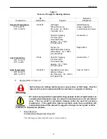
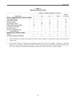
Table 13
Effect of Temperature on Insulation Resistance
Winding Temperature
Multiplying Factor to Obtain Insulation
(Degree C)
Resistance at 40
°
C (104
°
F)
80
10.00
70
5.50
60
3.10
50
1.70
40
1.00
30
0.55
20
0.31
10
0.17
Note that for a 104
°
F (40
°
C) decrease in temperature, the insulation resistance is increased by a mul-
tiplier of ten.
The insulation resistance of a machine is affected by its design. The insulation resistance of the ar-
mature circuit, corrected to 104
°
F (40
°
C), should measure at least 1.5 megohms. If measured value is
below 1.5 megohms, clean and re-test.
If the measurements are less than this limit, the machine should be dried or cleaned to attempt to in-
crease the insulation resistance. Regular, periodic measurements of insulation resistance can give a
useful indication of the rate of insulation system deterioration. External connections should be re-
moved to isolate the windings to be tested and megger value logged. A sudden drop or consistent
trend toward low values of insulation resistance, although possibly caused by moisture or contamina-
tion, generally gives evidence the insulation system is deteriorating and that failure may be imminent.
High-potential tests are not recommended on machines which have been in use. If such a test is made
immediately after installation, the test voltage should not exceed 85% of the original factory test of
two times the rated volts plus 1000 volts.
NOTE: Surge testing and AC impedance tests of windings to detect shorts should be performed by
trained personnel only.
M.
Cleaning of Windings
If windings become contaminated, suitable cleaning methods can be used to alleviate the problem.
The machine should be de-energized and slowly rotated by hand to permit maximum dust removal. Dry dirt,
dust or carbon should first be vacuumed – without disturbing adjacent areas or redistributing the contamina-
tion. Use a small nozzle or tube connected to the vacuum cleaner to enter into narrow openings (i.e., be-
tween commutator risers). A soft brush on the vacuum nozzle will loosen and allow removal of dirt more
firmly attached.
This vacuum cleaning may be supplemented by blowing with compressed air (air pressure should be in ac-
cordance with OSHA standards), which has passed through a dryer to remove moisture before entering the
motor.
Dirt can collect on the inside surface of the drive end coil support and on the underside of the armature coils.
This dirt can be easily removed with compressed air or a vacuum.
It is important to realize that when blowing out a machine, dirt may settle in a previously cleaned area and it
may be necessary to repeat the cleaning process to ensure that a thorough job is done.
Summary of Contents for GEH-5304A
Page 26: ...GEH 5304A 26 ues ...
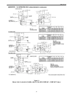
Page 34: ...GEH 5304A 34 Figure 3 Application Information for CD2512AT CD2813AT Frames ...
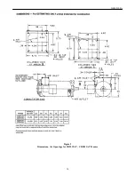
Page 36: ...GEH 5304A 36 Figure 5 Dimensions Air Openings for CD2512AT CD2813AT Frames ...
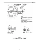
Page 38: ...GEH 5304A 38 Figure 6 Accessory Mounting CD2512AT CD2813AT ...
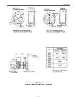
Page 39: ...GEH 5304A 39 Figure 7 Accessory Mounting CD2512AT CD2813AT ...
Page 40: ...GEH 5304A 40 ...
Page 43: ...GEH 5304A 43 Detach and fax or mail to the address noted above ...


