GE GDWT668V Technical Service Manual Download Page 20

– 20 –

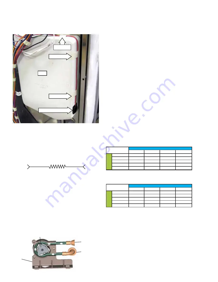
The routing of the DC wiring from the tank is very 
important. The 3 tape points on the tank keep the 
DC wiring perpendicular to the AC harness wiring 
running down across the front of the tank.

Tank

Sensor and Gasket

Tape Point

Tape Point

Tape Point

Note: The dispenser tank, sensor with wire harness, 
and gasket are only available as a complete 
assembly (Part # WD35X10058). They are shipped 
with a new dispenser tank retaining collar.

Detergent Level Sensor Strip Circuit

BRN/YELLOW

RED

DETERGENT

SENSOR

J4-3

J4-1

The dispenser pump operates on 120 VAC. During 
each prewash cycle, the pump is energized for 5 
seconds, dispensing 4 ml of detergent.

The electronic control uses two inputs to determine 
the total amount of detergent dispensed during the 
main wash cycle:

•  Soil level determined by the turbidity sensor
•  Water hardness as calibrated for the location

A water hardness selection mode permits the 
calibration of the water hardness for the location 
at installation. (See 

Water Hardness Test and 

Calibration

.)

To determine the amount of detergent to dispense 
during the main wash, the electronic control uses 
the following formula:

4 ml x Number of Prewashes

+ 25 ml + Additional Quantity for Hardness

The additional quantity is a predefi ned quantity 
of detergent based on the water hardness level 
programmed into the control.

Positive Displacement Pump

The SmartDispense positive displacement pump 
consists of a continuous fl exible tube running from 
the detergent reservoir to the inner door detergent 
outlet. The tube runs around the inside edge of the 
pump housing. A 3-roller impeller fi ts tightly into 
the center of the pump housing, with each of the 
3 rollers squeezing the sidewall of the tube. As the 
impeller is driven counterclockwise by the motor, it 
squeezes out a predetermined amount of detergent 
for each 1/3 revolution of the impeller.

Approximate Detergent Use

From

Detergent

Reservoir

To Detergent

Outlet

Pump 

Housing

Impeller

(Continued next page)

1

2

3

4

1

33

41

49

57

2

35.4

43.4

51.4

59.4

3

37.8

45.8

53.8

61.8

4

40.2

48.2

56.2

64.2

5

42.6

50.6

58.6

66.6

Smart Dispense Bottle Duration

1

2

3

4

1

10.3

8.3

6.9

5.9

2

9.6

7.8

6.6

5.7

3

9.0

7.4

6.3

5.5

4

8.4

7.0

6.0

5.3

5

8.0

6.7

5.8

5.1

Dosage (ml)

Har

d

ness

Soil Level

Hard

n

ess

Bottle Duration (wks)

Soil Level

Smart Dispense Dosage Amount

SmartDispense Dosage Amount

SmartDispense Bottle Duration

Summary of Contents for GDWT668V

Page 1: ...pany Louisville Kentucky 40225 31 9221 Top Control Stainless Steel Tub Dishwashers Technical Service Guide September 2011 GE Appliances GDWT668V GDWT768V PDWT180V PDWT380V PDWT560V PDWT565V CDWT280V C...

Page 2: ...s use WARNING To avoid personal injury disconnect power before servicing this product If electrical power is required for diagnosis or test purposes disconnect the power immediately after performing t...

Page 3: ...f the Bulk Dispenser Tank 21 Cycle Chart 12 Cycles 11 Detergent Rinse Module 24 Dishwasher Components 17 Door Handle 24 Door Switch Assembly 24 Drain Pump Assembly 35 Factory Test Mode 39 Fill Funnel...

Page 4: ...18 Sump Filter 29 Tactile Switch 23 Troubleshooting 37 Tub Gasket 27 Tub Thermal Cutout TCO 36 Turbidity Sensor 31 Upper Wash Arm 28 Vent Fan 25 Warranty 41 Water Hardness Test and Calibration 17 Wat...

Page 5: ...menclature Handle Control Location 0 Latch Front Control 6 Recessed Top Control 8 Towel Bar Top Control Door 8 Stainless Door Top Control T Top Control Serial Number The first two characters of the se...

Page 6: ...option and ActiveVent Fifty two dBA sound level ENERGY STAR qualified and CEE Tier II rated SmartDispense only on models GDWT7XX PDWT3XX PDWT5XX CDWT980 and ZBD89XX Weights and Dimensions Approximate...

Page 7: ...n See SANITIZE below for complete cycle description Opening the door or pressing any key while the door is closed and latched will turn off the light CLEAN Displayed when a wash cycle is complete Refe...

Page 8: ...8 Continued next page...

Page 9: ...inued next page The STEAM option will use the heater to increase the temperature of the water The circulation pump will turn off periodicall allowing water to drip onto the hot calrod which will creat...

Page 10: ...10 Start 5...

Page 11: ...4 times Disabling STEAM will shorten the cycle time If STEAM is selected during NORMAL or AUTO cycles turbidity response is ignored and cycle defaults to the heavy soil algorithm HEATED DRY takes 34 m...

Page 12: ...e low flow water valve sec 62 16 62 21 62 23 Fill Time high flow water valve sec 46 13 46 15 46 17 Drain Time sec 7 75 10 75 11 105 Max Temp Limit F 158 158 158 Min Temp Limit F 120 120 Extend Time mi...

Page 13: ...13 Front View Component Locator Views Control Panel View Insulation Access Panel Continued next page Door Latch Control Panel Door Panel Control Assembly...

Page 14: ...nterior View Without Racks Detergent Rinse Module Compartment View Detergent Rinse Module Detergent Compartment Compartment Lid Rinse Agent Cap Rinse Agent Outlet Continued next page Indicator Window...

Page 15: ...iew Insulation Removed Bottom View Looking Up Spray Arm Heating Element Fill Hose Fill Funnel Front Back Drain Pump Tub TCO Coarse Filter Float Dome Fine Filter Hub Nut Door Spring Sump Water Valve Mo...

Page 16: ...16 Control Board Connector Locator View J5 J7 J3 J2 J1 J5 Active Vent J7 Keypad J1 Power Supply J2 Power Switching J3 Turbidity Temperature Sensor...

Page 17: ...s from the outer door panel Caution Carefully remove the outer door from the inner door frame 4 Disconnect the wire harness from the tactile switch Disconnect Water Hardness Test and Calibration Test...

Page 18: ...ate the lights on the control panel 1 Press the SELECT CYCLE and DELAY HRS buttons simultaneously and hold for 3 seconds 2 The current hardness setting is shown on the TIME REMAINING display 3 Enter t...

Page 19: ...harness When the detergent in the reservoir drops below the continuity sensor a signal is sent to the control board and the LOW DETERGENT LED indicator light is turned on The light indicates 3 to 7 wa...

Page 20: ...the electronic control uses the following formula 4 ml x Number of Prewashes 25 ml Additional Quantity for Hardness The additional quantity is a predefined quantity of detergent based on the water ha...

Page 21: ...and HEATED DRY LEDs are off 6 Dishwasher runs a complete cycle with the main motor instead of the dispenser tank Cycle is complete when the CLEAN light illuminates This should take approximately 60 m...

Page 22: ...control board to the turbidity sensor can be tested by checking the voltage at J3 on the control board See Control Board Connector Locator View A pulsed 2 VDC signal should be measured across wires J...

Page 23: ...console Note When replacing the tactile switch transfer the model select plug to the new switch Tactile Switch Buttons Silicone Pad Model Select Plug Lens The lens is located behind the console and at...

Page 24: ...ips head screws from the door switch Door Handle The door handle is held in place by 2 screws that can be accessed by removing the console To remove the door handle 1 Remove the console See Lens steps...

Page 25: ...2 in the center of the connecting rod At the second activation of the module the lever lifts the connecting rod by the notch This action lifts the rinse dispenser plunger 3 and releases the rinse age...

Page 26: ...nt motor turns the active vent switch clockwise to close the vent and counterclockwise to open the vent To remove the active vent 1 Remove the vent fan See Vent Fan steps 1 3 2 Disconnect the active v...

Page 27: ...See Outer Door Panel 2 Pull the wire rod out of the gasket Bottom Door Seal The bottom door seal is riveted to the inner door panel To remove the bottom door seal replace the inner door panel See Inn...

Page 28: ...opening the dishwasher door and removing the bottom rack Remove the lower wash arm by pulling it up while turning it counterclockwise Upper Wash Arm Remove the upper wash arm by removing the 1 4 in he...

Page 29: ...he lower wash arm See Lower Wash Arm 2 Rotate the hub nut counterclockwise Lift the hub nut off the fine filter 3 Lift the fine filter off the wash arm hub Sump Filter The sump filter prevents large p...

Page 30: ...r putty knife Tab Tab Coarse Filter To remove the coarse filter 1 Remove the sump filter See Sump Filter 2 Turn the wash arm hub counterclockwise and remove it from the tub 3 Lift the coarse filter fr...

Page 31: ...um number of wash and rinse fills for the selected cycle The turbidity sensor can be tested by checking the resistance across the wires on the control board at J3 pin 1 yellow black wire and J3 pin 4...

Page 32: ...ure the O rings are placed between the heating element and tub floor before installing the heating element nuts O ring Disconnect Tab Disconnect Disconnect To remove the turbidity sensor 1 Remove the...

Page 33: ...s electronically controlled and solenoid operated The flow of water is controlled by a rubber flow washer capable of maintaining a flow rate of 1 1 to 1 3 gallons per minute with incoming water pressu...

Page 34: ...the water inlet valve bracket Caution To prevent water leakage assure the O ring is retained in the valve before installing the bracket O Ring 3 Remove the two 5 16 in hex head screws from the water...

Page 35: ...ation 3 Lay the dishwasher on its back 4 Disconnect the 2 wires from the drain pump 5 Loosen the 5 16 in hex head screw then pull the drain pump off the sump Disconnect Disconnect Motor Pump Assembly...

Page 36: ...ehind the toe kick panel To remove the tub TCO 1 Disconnect power 2 Remove the two 1 4 in hex head screws and the access panel 4 Slide the tub TCO off the bracket 3 Remove the two 1 4 in hex head scre...

Page 37: ...ically exit service mode if the control panel is inactive for 5 minutes Troubleshooting Service Mode Control Operation When a control is activated in the service mode the output continues to remain ac...

Page 38: ...38 Top Control Activates Deactivates fan Hold both buttons simultaneously for 3 seconds...

Page 39: ...onds When second fill starts exit test mode by pressing the START RESET button In some cases it may be necessary to unplug the unit to exit the test mode If the unit is left in factory test mode the d...

Page 40: ...M J2 11 J2 10 DOOR INTERLOCK WATER VALVE DOOR INTERLOCK J2 5 PX FLOOD SWITCH WX 725 1200 C NO PUMP MOTOR J2 4 M CIRCULATION PUMP WX NX 10 HEATING ELEMENT J2 6 J2 7 VX VX VX WX HEATING ELEMENT FAN J2 3...

Page 41: ...ery including damage from items dropped on the door This warranty is extended to the original purchaser and any succeeding owner for products purchased for home use within the USA If the product is lo...

Reviews: