


15
English
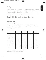
Installation Instructions
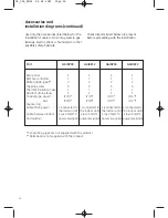
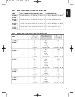
Accessories and
installation diagrams
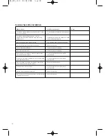
Use only the accessories listed below for the
installation. Failure to do so may lead to gas
leakage, electric shock
, a fi
re hazard or other
possible safety hazards.
Check all parts listed below are present
before proceeding with the installation.
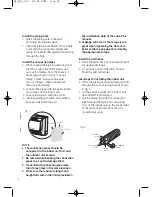
Warning
Immediately stop all operations, disconnect
the power and contact your nearest service
center in the event any of the following
happens:
• Unusual noise while the unit is operating
• Power fuse or breaker switch repeatedly
activates
• W
ater or fluid splashes into the unit
• Electrical wirings and power plug become
very hot
• An unpleasant smell is emitted during
operation
GE_SAC_ENGL 01-02-2011 Page 15
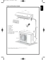
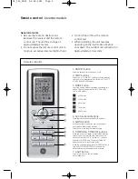
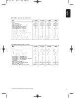
Part
Rear panel
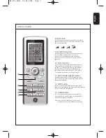
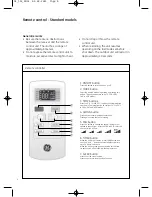
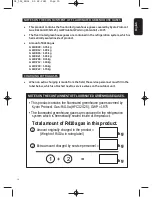
Remote controller
Battery (AAA type)**
Tapping screw
Thermal insulation hose
Outdoor drain elbow
Copper pipe, Liquid
Gas
Square ring
Cable, Main power
Cable, between indoor
and outdoor
* Connecting pipes are not supplied with the product.
** Batteries are not supplied with the product.
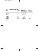
GAIRB09
1
1
2
5
1
1
(1/4”)*
(3/8”)*
1 (connected to
the indoor unit)
1 (4x1.5mm
2
,
power & signal)
GAIRB12
1
1
2
5
1
1
(1/4”)*
(3/8”)*
1 (connected to
the indoor unit)
1 (4x1.5mm
2
,
power & signal)
GAIRB16
1
1
2
5
1
1
(1/4”)*
(1/2”)*
1 (connected to
the indoor unit)
1 (4x2.5mm
2
,
power & signal)
GAIRB21
1
1
2
5
1
1
(1/4”)*
(1/2”)*
1 (connected to
the indoor unit)
1 (4x2.5mm
2
,
power & signal)


