background image

Everest Ca-Zoom

®


6.2

46

Operations

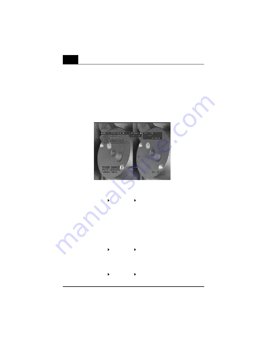
Live/FF Split Screen

  •  Initially, the left half screen is active with a live image present.

Split Screen Menu Options

Pressing the 

MENU

 button while in split screen allows you to choose to:

  •  Switch active sides
  •  Close either side
  •  Select either side for a full-screen view.

Split Screen Menu

Activating Other Half Screen

  •  Press 

MENU

 button. The split screen menu options screen will appear.

  •  Highlight SPLIT OPTIONS   (RIGHT or LEFT)   ACTIVE.
  •  Press the 

ENTER

 button

  •  The frozen half screen is now active, and the joystick controls panning within the frozen  


   image.

Freezing Live Half Screen

  •  When the live half screen is active, the live image may be frozen by pressing the 

FREEZE

.

Closing Other Half Screen

  •  Press 

MENU

.

  •  Highlight SPLIT OPTIONS   (RIGHT or LEFT)   CLOSE.
  •  Press

 ENTER

.

Show Active Side As Full Screen

  •  Press 

MENU

.

  •  Highlight SPLIT OPTIONS   (RIGHT or LEFT)    FULL SCREEN.
  •  Press 

ENTER

.

Figure 23

Summary of Contents for Everest Ca-Zoom 6.2

Page 1: ...GE Inspection Technologies Remote Visual Inspection Everest Ca Zoom 6 2 Operating Manual www ge com inspectiontechnologies ...

Page 2: ...Inspection System the newest innovation in remote visual inspection Thank you for your business This manual provides you with all necessary information you need to operate and maintain the Everest Ca Zoom 6 2 Digital Inspection System The manual will assist you to optimize your inspections and was developed to help all levels of operators learn quickly and precisely In addition the manuals appendi...

Page 3: ...PLIT SCREEN 45 12 6 VIDEO RECORD 48 12 7 FILE MANAGER Menu 50 12 8 SETUP Menu 58 Table of Contents 13 Measurement Operations 67 14 Maintenance 71 14 1 Cleaning 71 14 2 Storage Shipment 71 14 3 Lamp Lamp Window Replacement PTZ140 71 14 4 Camera Window Replacement PTZ140 72 14 5 Camera Module Replacement PTZ140 73 14 6 Lamp Window Replacement PTZ100 75 14 7 Camera Window Replacement PTZ100 76 14 8 C...

Page 4: ...le parts inside the CCU The CCU should never be forced open or misused The Hand held Controller housing and cable connectors should never be exposed to hazardous environments There are no serviceable parts inside these mentioned components Refer all service to listed Service Centers see Service Environmental The Everest Ca Zoom 6 2 Digital Inspection System camera head and cable are for in air or ...

Page 5: ... Inspection System may be disconnected from the AC power main supply by disconnecting the power cord from the main power source Warning Image may become distorted and unuseable between 95 and 145 MHz at a field strength of greater than 10V M Warning Parallel Laser Accessory avoid inadvertent exposure to hazardous laser radiation Prevent direct eye exposure to beam Ensure that the beam is always te...

Page 6: ... requièrent de service L unité de contrôle informatiseé ne doit jamais être ouverte de force ni faire l objet d une mauvaise utilisation Le boîtier du moniteur et les connecteurs du câble ne doivent jamais être exposés à un environnement dangereux Il n y a aucunes pièces qui requièrent du service à l intérieur de ces composantes Référer toute demande de service à la liste des centres de services v...

Page 7: ...pment ou donner des chocs électriques à l opérateur Le systèm d inspection digital Everest Ca Zoom 6 2 peut être débranché du courant d alimentation CA en débranchant le cordon d alimentation de la source de courant Avertissement L image peut devenir déformée et inutilisable entre 95 et 145 Mhz dans des champs de plus de 10V M Avertissement Pointeurs laser parallèles exposition à de la radiation l...

Page 8: ...ENT ÊTRE CHAUDES INFORMATION SUR LE FUSIBLE REMPLACEZ UNIQUEMENT AVEC LE MÊME TYPE ET MÊME CAPACITÉ Description des Symboles 10AF 250V 10AF 250V Caution Use of controls or adjustments or performance of procedures other than those specified herein may result in hazardous radiation exposure ATTENTION L utilisation de contrôle d ajustement ou de procédures autres que celles précitées peuvent causer u...

Page 9: ...ntrol zoom lighting image control and extensive menu functions for image management Dual function joystick for camera movement and software menu control and an on board file manager Measurement capability with parallel laser accessory mounted on the camera head provides a reference measurement on a perpendicular surface Portable shipping case just plug it in and in 30 seconds you re ready to inspe...

Page 10: ...ion Clean the camera window regularly In most cases a poor image is due to dirt on the camera window lens Always allow sufficient time for camera head to cool before placement in storage shipping case iVIEW Hand Held Controller Camera Control Unit CCU Rugged Shipping Storage Case Wheels Retractable Case Handle Ca Zoom Camera with Integrated Lights and Pan Tilt comes with PTZ140 and or PTZ100 and o...

Page 11: ...etup instructions Shipping Storage Case 6 3 Optional Components Parallel Laser Measurement Accessory PTZ140 PTZ100 iVIEW Remote Software for Controlling Ca Zoom camera from a PC Sony GV D1000 Digital VCR CO2 Pressurization Kit Telescoping and Interconnecting Poles Tripod Swivel Manway Tripod Rackmount Consoles Cable Reel Camera Head Stand Keyboard Extension Cables for Operation up to 500 m 1640 ft...

Page 12: ...board Connection Coaxial Video Out S Video Out Coaxial Video In S Video In USB Video Output Hand held Controller Connection Camera Connection System Power On Off 7 2 Camera Head Options AC Power RS 232 Cable Pan Tilt Housing 2 X 35 Watt Lights Schrader Valve Cap Camera lens Pan Tilt Housing Schrader Valve Cap Camera lens 4x5W LED Lights PTZ140 PTZ100 CompactFlash Drive AC Fuse ...

Page 13: ... 2 8 4 5 Lights Image Focus Multi function joystick Exit Enter Menu Freeze Save Power LCD Audio Level Zoom Microphone 7 2 Camera Head Options Continued Pan Housing 8 X 5 Watt Lights Schrader Valve Cap Camera lens PTZ70 Tilt Mechanism LDC Monitor Speakers Soft Buttons 8 total ...

Page 14: ...the Hand held Controller and push in The ferrite bead on the cable is to be oriented toward the Hand held Controller Step 3 Attach the other end of the Hand held Controller cable to camera control by align ing the red dot on the cable to the small keyway on the CCU Before setting up the system for use make sure the CCU Camera Head and Hand held Controller are placed on a sturdy surface 8 1 Attachi...

Page 15: ...e a slack loop between collar and camera head Step 6 Tighten collar screws Figure 4 8 2 Attaching Camera Cable to Camera and CCU Step 1 Align the small key on the cable connector with the keyway inside the connec tor on the camera head Push the cable in and turn the nut until it comes to a hard stop fig 2 Note If the nut does not reach a hard stop the cable may not be aligned correctly Realign the...

Page 16: ... receptacle in the front of the CCU Connect the opposite end of the same video cable to the appropriate video in receptacle of the output device Input Devices For connection of input devices determine the type of video cable required for connection S Video or coaxial BNC Connect the end of the video cable to the appropriate video in receptacle in the front of the CCU Connect the opposite end of th...

Page 17: ... the mounting plate over the end of the harness Make sure the O ring is in place on laser mounting plate fig 8 Step 5 Connect to mating connector from camera head fig 9 Step 6 Align the mounting holes in the laser attachment with the mounting plate and thread holes in the camera housing Place laser attachment flush to mounting sur face and tighten mounting screws fig 10 In order to insure the inte...

Page 18: ...late on camera head fig 12 Step 4 The laser accessory has a wire and connector assembly Connect to mating con nector from camera head fig 13 Step 5 Make sure the o ring is in place on laser mounting plate Place laser accessory flush to mounting plate surface and tighten mounting screws fig 14 In order to insure the integrity of the camera system with laser accessory the camera head needs to be pre...

Page 19: ...ld Controller and CCU 4 Connect camera cable to camera and CCU 5 Attach strain relief cable 6 Place camera on mounting pole 7 Insert new a CompactFlash card into the CompactFlash drive 8 Connect other peripherals as needed 9 Turn on the green power switch When system power is on the green power switch will illuminate 10 Allow approximately 30 seconds for software boot 11 Your are now ready for you...

Page 20: ...intuitive up down left and right joystick movements Joystick Menu Navigation The joystick is used to navigate through the various menus Up Down joystick movements navigate up and down the menu while Left Right joystick movements access drop down menu features which appear on screen associated with primary menu options Menu Access Press MENU button Menu Navigation Use joystick to move the cursor to...

Page 21: ... the left edge and 4 on the right edge of the LCD Soft buttons are labeled and remain visible on screen when the feature is available The feature label will disappear after several seconds have passed since button s was last pressed Usage These buttons are used to activate the on screen soft buttons prompts which are located directly next to the soft buttons Access Press the soft buttons associate...

Page 22: ...en for 3 seconds after the Zoom Plus or Zoom Minus buttons have been pressed The zoom level gauge line will increase or decrease indicating the relative zoom level Soft button TOGGLE DIGITAL ZOOM will be displayed When digital zoom is turned off Zoom will stop at the limit of the optical zoom as indicated by the white line in the zoom level gauge and TOGGLE DIGITAL ZOOM will not appear When digita...

Page 23: ...r FOCUS or button has been pressed Camera will stay in manual focus mode after the indicator gauge disappears Soft button RETURN TO AUTO FOCUS will be displayed Pressing soft button will return camera to auto focus mode and focus level gauge will dis appear Steering Steering capabilities will be operational in manual focus mode Storing Images may be saved while using manual focus Freezing Images m...

Page 24: ...n Displays light level gauge bar in top right corner of screen showing relative light level name of light Right or Left and type of lamp being controlled as defined in Camera Setup menu When the system is in light mode the light level indicator will be displayed in the top right corner of the screen for 3 seconds after the Light button has been pressed Soft buttons FULL ON LAMP UP LAMP DOWN FULL O...

Page 25: ...ve image brightness Soft button FULL AUTO will be displayed Pressing soft button will return image brightness control to auto mode Exit Wait for soft button operation to time out Save Usage Saves current on screen image to last accessed directory May be a live or frozen image Access Press Save button in Live or FF screen Exit Image will be frozen if image is not previously frozen and save will be ...

Page 26: ...nctions To Exit Menu Pressing MENU again exits this menu and returns you to the live image To Exit FF Press FREEZE again or EXIT button to return the system to live mode Power Usage Enter low power consumption mode by powering down the Hand held Controller including the LCD and the lights on the camera head The rest of the system will remain active Note Lights do not return to their previous setti...

Page 27: ...cessed through a combination of button activations and onscreen menu selections Onscreen menus are accessed by pressing the MENU button Each menu appears over the image and temporarily displaces any overlays in the menu Some buttons only work in specific modes If you press a button that does not have a function for the mode you are in a message indicating this will be displayed briefly Some menu f...

Page 28: ...d measurement cursors Only frozen images may be stored Images with measurement annotations may be saved After performing measurement operation press MENU to access storage options Storage Media Images and videos captured by the PTZ system may be stored in the internal system flash memory located in the CCU or on CompactFlash card use 4X or higher speed CompactFlash card for video recording Images ...

Page 29: ...ozen images Measurement images may be saved after measurement has been performed Basic Operation From a frozen image screen press MENU The menu associated with that frozen screen will appear Use the joystick to move the arrow pointer to select the memory location where you would like to store the image Saving You have a choice of saving images and videos in one of two active folders An internal C ...

Page 30: ...Audio Annotation Usage Allows up to 15 seconds of audio information to be recorded and associated with a stored image file Access An audio file may be created immediately after storing an image by following the on screen instructions From live viewing press FREEZE button The image will freeze and FF will appear in the upper right corner of the screen An audio file may be created any time a stored ...

Page 31: ...to select and the ENTER button to recall an image to full screen Press MENU Highlight AUDIO A drop down menu will appear Use the arrow pointer to select RE RECORD AUDIO Press ENTER A menu will appear with Audio Already Exist For This Image Do You Wish To Overwrite Press ENTER to begin re recording audio Text Annotation Usage Allows text characters to be displayed on live and still frozen images an...

Page 32: ...er is selected the cursor automatically moves to the next character entry position To backspace or navigate between lines use the arrows in the on screen key board window Use of an External Keyboard to Generate Text In any screen which requires text generation Plug in a PS 2 compatible keyboard into the keyboard connector located on the camera control unit labeled Keyboard Note the keyboard may be...

Page 33: ...need to create a new preset text press MENU You can then create edit or delete existing preset text screens Press ENTER to select a preset text to add to the frozen image The position of the two lines of preset text may be chosen by using the joystick to move the text within the image Press ENTER when the text is positioned properly Proceed with the process to save the image Clearing Text Annotati...

Page 34: ...TION ADD TEXT Press ENTER You may now use the joystick or external keyboard to add text Press ENTER when all text has been entered Recalling Preset Text for Live Annotation In a live screen press MENU Use the arrow pointer to highlight LIVE ANNOTATION ADD PRESET Press ENTER Use the joystick to toggle between the available preset text options Note If you need to create a new preset text press MENU ...

Page 35: ...erest Arrow annotation may be added to an image During live image viewing When the image is frozen prior to storing the image On a recalled image Access On a live frozen or recalled image Press MENU Highlight LIVE ANNOTATION or STILL ANNOTATION A drop down menu will appear which includes ADD ARROW Operation to Place Arrows Move the arrow pointer cursor to ADD ARROW Press ENTER An arrow will appear...

Page 36: ...tion At any time for live image arrow annotation or prior to saving a frozen image all current text and arrow annotation may be cleared by Press MENU Highlight LIVE ANNOTATION or STILL ANNOTATION Move the arrow pointer to CLEAR ARROWS Press ENTER ...

Page 37: ...NS SPLIT SCREEN LIVE ANNOTATION VIDEO RECORD FILE MANAGER SETUP MENU Figure 20 12 Main Menu Operation Live Main Menu Screen Access Main Menus While in live or FF viewing mode press MENU button Use cursor to select menu or function Sub menus may drop down associated with primary menu items To Select Use joystick to move the cursor to desired item Press the ENTER button To Exit Press the MENU button...

Page 38: ... Home Postion configured in Presets Home Position Set Home 12 2 CAMERA SETUP Menu Usage The Camera Setup Menu is used to change the PTZ s camera configurations Access Press MENU Highlight CAMERA SETUP Press ENTER Operation A menu titled CAMERA SETUP see example screen shown below will appear See individual feature descriptions for use of each menu function Exit Press MENU button again or press EXI...

Page 39: ...ith optical and digital zoom Use of soft button Toggle Digital Zoom enables camera operation in digital or optical zoom mode If Permanent OFF was selected Camera will operate in optical zoom mode only TOGGLE DIGITAL ZOOM will not appear Invert Camera Usage Allows user to invert camera image or camera joystick position control Access Highlight Invert Camera Operation Move pointer arrow to either IM...

Page 40: ...Control Operation Move pointer arrow to either ON or OFF Press ENTER A check mark will appear next to your selection To Accept Press MENU Operation to setup Manual Image Control Press image button on Hand held Controller Soft buttons will appear on the LCD Use soft buttons for selection of individual control of BRIGHTNESS SHUTTER IRIS GAIN The Brightness function is a predetermined combination of ...

Page 41: ... Highlight Sensor Display Operation Move pointer arrow to Pressure Pan Tilt or Radiation Move pointer arrow ON or OFF Press ENTER A check mark will appear next to your selection To Accept Press MENU Temp Sensor ICON On Off Allows thermometer icon on the PTZ s LCD to be turned on or off Access Highlight TEMP SENSOR Move the pointer arrow to ICON A drop down menu with ON OFF appears Press ENTER A ch...

Page 42: ...and thermometer icons Exceeding Limit Red warning and thermometer icons 2 An audio warning will simultaneously beep if audio warning is enabled Pan Tilt Range Usage Allows user to set pan tilt for 0 360O or 180O Access Highlight Pan Tilt Range Operation Move pointer arrow to 0 360 180 or REVERSE DIRECTION Press ENTER A check mark will appear next to your selection To Accept Press MENU IR Filter PT...

Page 43: ...ance Operation Move pointer arrow to either AUTO or PUSH TO SET Press ENTER A check mark will appear next to your selection To Accept Press MENU Lamp Setup Usage Allows user to setup lamp type that is installed on camera head and the lamp type is dis played when the lamp controls are active Access Highlight Lamp Setup Operation PTZ100 PTZ70 Move pointer arrow to BOTTOM or TOP Move pointer arrow to...

Page 44: ... page 67 for Measurement Operation 12 4 POSITIONS Allows presetting of HOME ZERO and ten other unique positions and magnification levels Alllow convenient renaming and access to previously preset positions Home Position Menu Feature Allows user to save a position that is used often and be commanded to return to that position Set Home position Use joystick to position camera to desired home positio...

Page 45: ...era position and zoom magnification level Preset 1 10 Menu Feature Allows creation of ten presets with names Go to Preset Move pointer arrow to a PRESET button 1 10 Move pointer arrow to GO TO PRESET Press ENTER Operation Camera will move to Preset Postion previously configured Rename Preset Usage Allows renaming of presets 1 10 of up to fifteen characters Rename Preset Access Move pointer arrow t...

Page 46: ...ve or frozen image in any com bination of live frozen and recalled images except live live Access Press MENU button while in the live freeze frame or recalled image modes Use cursor to select SPLIT SCREEN Press ENTER button Initially a frozen image of the previously shown full screen image is shown on the right half screen and a half screen view of the previously shown full screen image a live fre...

Page 47: ...ess MENU button The split screen menu options screen will appear Highlight SPLIT OPTIONS RIGHT or LEFT ACTIVE Press the ENTER button The frozen half screen is now active and the joystick controls panning within the frozen image Freezing Live Half Screen When the live half screen is active the live image may be frozen by pressing the FREEZE Closing Other Half Screen Press MENU Highlight SPLIT OPTIO...

Page 48: ... ENTER Recalling a Stored Image to a Half Screen Activate the side into which you want to recall an image Press MENU Highlight FILE MANAGER Press ENTER The FILE MANAGER menu will appear Highlight RECALL IMAGE Use the arrow pointer to select the source of the image to be recalled either C or A Press ENTER Navigate through the folders and thumbnail images to select the desired image Press ENTER The ...

Page 49: ...ghlight Stop Filename Press ENTER or During recording press any of the soft buttons The video record settings will appear Press Stop soft button RECORDING OPTIONS The Recording Option mode displays video quality settings memory space on the A or C drives and allows for renaming of video and to start recording Access Press MENU while in live mode Highlight VIDEO RECORD by using the cursor to move t...

Page 50: ...choose into which drive the video file is to be stored Access Highlight Save Location Move pointer arrow to either C or A Or choose a folder in C or A Press ENTER Name Video Option Allows for naming renaming of video before being recorded Access Highlight Name Video Press ENTER Operation A screen appears with blinking cursor Move joystick up or down to select characters Move joystick left to modif...

Page 51: ...d WAV file it will also be operated on in the same manner as the image file which is selected File folder creation renaming and deletion are accessed through this menu CompactFlash card erase function is available through this menu Access Press the MENU button Highlight FILE MANAGER with the cursor Press ENTER Operation A menu titled FILE MANAGER as shown above will be displayed See individual fea...

Page 52: ...he image or video to be displayed by moving the joystick left right or up down A box will appear around the selected image and the file name will highlight To access the next page of thumbnail images keep moving the cursor down To return to the previous page move the cursor up Once the desired image or video has been located press ENTER The image will then be dis played full size with the file nam...

Page 53: ...UP MENU may also be accessed from the RECALLED menu COPY TO A Function Usage Allows images captured and stored in the C internal memory of the PTZ system to be exported to a PC or other devices using a CompactFlash card inserted into the CCU s CompactFlash drive Images from the thumbnail pages can be selected and then copied to card Access Access the FILE MANAGER menu Select COPY TO A from the Fil...

Page 54: ... returned to the screen from which the File Manager menu was selected If the card becomes full a message will appear and prompt the user to insert another card After insertion of the new card press ENTER to resume or MENU to cancel Operation for Copy Folder to CompactFlash Card If COPY TO A FOLDER was chosen A page of thumbnail file folders will appear Select the folder to be copied to A drive by ...

Page 55: ...n the top left corner of the image To remove a check mark press ENTER again Repeat the process until all images and videos that need to be deleted have been checked Press MENU A message will display asking Are sure you want to delete Press ENTER to delete selected images The selected images and videos will be deleted and you will be returned to the screen from which FILE MANAGER was selected Exit ...

Page 56: ...EATE Press ENTER Thumbnail images of the current folders on the chosen drive appears on screen along with a new unnamed folder The new folder has a blinking letter cursor in the folder name You may modify the folder name by using the joystick or an external keyboard Note Spaces are not allowed in folder names Press the ENTER key on the handpiece to save the folder name A new screen appears which a...

Page 57: ...press EXIT to return to the previous screen CHOOSE FOLDER Usage Whenever a frozen image is saved there are two possible locations where the file may be saved A folder in the C memory or A folder in the A memory A specific folder name in each drive may be chosen in advance such that the next time an image is being saved the chosen folders are listed as the target storage locations Note If a folder ...

Page 58: ...NTER to complete the folder delete process You may continue to delete folders using the above process or press EXIT to return to the previous screen ERASE A Operation Usage Erase all files stored on a CompactFlash card in the A drive so that new files may be stored on that device Access Highlight ERASE A in the FILE MANAGER menu Operation Press ENTER A screen will appear asking if you wish to proc...

Page 59: ... the onscreen display Press ENTER A list of user modifiable fields will appear Operation Move the joystick such that the small arrow pointer is located next to the setting you would like to modify or the process you wish to activate Press ENTER to choose a new setting To Accept Press MENU or see specific onscreen SETUP MENU topic instructions To Cancel Press EXIT Exit Press EXIT 12 8 SETUP Menu Se...

Page 60: ...red To Accept Press ENTER to choose the new language Press MENU to accept the menu choice and return to the screen you were in prior to accessing the SETUP Menu LOADING LANGUAGE FILES New language files may be loaded via the setup menu language feature Only language files supplied by GE Inspection Technologies or a GE Inspection Technologies authorized representative should be loaded into the PTZ ...

Page 61: ...mode Allows the selection of MPEG video format Allows the selection of video quality Allows the selection of video record time limits Notes A bitmap image consumes up to 48 times as much memory as a low quality JPEG image A high quality JPEG image consumes up to 4 times as much memory as a low quality JPEG image See Image Storage for specifications for total image storage capacity in each video fo...

Page 62: ...ation Move pointer arrow to NONE 1 MIN 5 MIN 10 MIN 20 MIN Press ENTER A check mark will appear next to your selection To Accept Press MENU GRAPHICS Usage Allows the selection of text color and text shadowing Allows the creation or editing of up to 40 preset text annotation overlay screens of 2 lines x 30 characters per line Allows a logo bitmap file to be imported and displayed on all live and sa...

Page 63: ...RESETS Create New Preset Text Overlay Screen Up to 40 2 line x 30 characters per line text overlay screens may be created and stored in memory for use as live video overlay annotation text or with captured video images Access Highlight GRAPHICS A drop down menu will appear Move pointer arrow to PRESETS Press ENTER If there are any existing text overlay screens in memory the last screen created wil...

Page 64: ...arrow to LOAD Press ENTER Load Logo Operation The logo file is now stored in the internal memory of the PTZ system only one logo file may be stored To Accept Press MENU Logo On Off Operation Move the pointer arrow to ON or OFF Press ENTER A check mark will appear next to your selection To Accept Press MENU TIME DATE Note Time is always shown in military 24 hour format Date is always shown in day m...

Page 65: ...llows the measurement system to display results in inches in or millimeters mm Access Highlight MEASURE Move pointer arrow to UNITS A dropdown menu with IN MM will appear Mover pointer arrow to desired measurement unit type MM or IN Press ENTER A check mark will appear next to your selection To Accept Press MENU Menu Feature USER PROMPTS Usage Allows advanced users to disable user blue warning scr...

Page 66: ...EEP Move the arrow pointer to ON or OFF and press ENTER to make selection To Accept Press MENU Or press EXIT to cancel SYSTEM INFO Menu Feature Provides total Flash memory capacity and amount of remaining free Flash memory for image and audio file storage Provides a display of the software revision level of the various microcontrollers and main computer in the PTZ system Access Highlight SYSTEM IN...

Page 67: ... the main program memory card into the CompactFlash drive on the CCU Press ENTER The PTZ system will search for updated software If update files are detected press ENTER The system will then automatically install the software if software is not found the PTZ system will prompt you to press ENTER to terminate the update process After the update is successfully loaded Update Successful will be shown...

Page 68: ...d in cursor placement the optional Parallel Laser accessory provides a reference measurement on a perpendicular surface Refer to page 43 for instructions on operating the laser accessory Although their accuracy is limited comparison measurements are useful if you want to check the approximate size of many items quickly Comparison measurements begin by establishing a known dimension as a reference ...

Page 69: ...ENTER Instructions will appear to enter the value of the know reference dimension Use the joystick to increase or decrease the value and press ENTER Comparison Measurement Length Usage Allows length measurements of frozen images based on known dimensions Operation Set the reference dimension as General Operation One cursor will appear Place the first cursor and press ENTER Place the second cursor ...

Page 70: ... flashing background Use the joystick to reposition the number and press ENTER The length of the reference line is also displayed on the side of the image Comparison Measurement Area Usage Measure the Area in square inches or square millimeters of a feature based on a known ref erence dimension on the image Operation Set the reference dimension as described in General Operation The first of up to ...

Page 71: ... flashing background Use the joystick to reposition the distance if desired and press ENTER Press MENU to save or make additional Comparison measurements Comparison Measurements Circle Gauge Usage Creates a circle on the image of known size to compare features based on a known reference dimension in the image Operation Set the reference dimension as described in General Operation Follow onscreen i...

Page 72: ...mera system is turned off and be sure to de pressurize the camera unit via the Schrader valve see page 11 Make sure unit is cooled down completely Lamps are extremely hot 14 Maintenance 71 To replace the lamp window follow these steps Remove the lamp window retaining ring by gently prying the end of the ring with a small screwdriver Gently pry the window out of the housing Carefully remove the o r...

Page 73: ... and turn clockwise by hand until the cap fits snugly against the housing There should be no gap between the cap and the housing when finished 14 4 Camera Window Replacement PTZ140 CAUTION Before performing any maintenance task be sure to de pressurize the camera unit via the Schrader valve see page 11 To replace the camera window follow these steps Remove the camera window retaining ring using th...

Page 74: ...mera housing by unscrewing them counterclockwise fig 37 Remove 2 small camera module mounting screws found on the bottom of the camera hous ing fig 38 Pull the module out through the front of the camera housing Make sure not to smudge or dirty the lens Unplug all of the harnesses attached to the camera module CAUTION Pay attention to where the connectors go There are two 2 pin connectors to attach...

Page 75: ...acks back into the camera housing One on each side of the camera fig 42 Replace the 2 camera module mounting screws Replace front and back cover of housing Make sure o rings are clean lubricated and seated properly in the grooves Make sure not to knick the o rings There should be no gap between the back and front covers when finished Pressure test camera housing See Pressure Testing section on pag...

Page 76: ...the five screws with a Phillips screwdriver Carefully remove the o ring and windows using the supplied o ring pick Clean o ring groove thoroughly Replace lamp window Replace o ring with a new well lubricated o ring by pressing into gap between the window and housing Use a small flat tipped screwdriver as neccessary Install the window retainer with the five screws Tighten down evenly Pressure test ...

Page 77: ... using the by gently prying the end of the ring with a small screwdriver Gently pry the window out of the housing Carefully remove the o ring from the groove with the supplied o ring pick Clean o ring groove thoroughly Replace o ring with a new well lubricated o ring Replace camera window Install retaining ring by starting on one end and working around the camera housing until the entire ring is i...

Page 78: ...amera housing by unscrewing the 8 Phillips screws around the edges fig 51 Lift off cover by applying some pressure to slide it sideways Locate the video harness and pull free from camera housing fig 52 Detach black video connector harness and gently pull to the left side out of the way fig 53 Locate the power harness and unplug from the circuit board by gently pulling on the wires fig 54 Gently pu...

Page 79: ...ng fig 57 As the module is removed pull to the left to clear the internal wiring Make sure the internal wiring is tight along the sides of the housing before inserting a new module fig 58 Reconnect the video harness the power harness right 4 pin connector and the laser harness left 4 pin connector Replace cover and tighten screws hand tight Pressure test camera housing See Pressure Testing section...

Page 80: ...read the knurled ring on the back of the camera housing fig 61 Gently pull the front half of the housing away from the rear half DO NOT TRY TO ROTATE THE TWO HALVES THEY ARE KEYED fig 62 Disconnect the wiring harnesses fig 63 Unplug the wire fro the back of the LED that needs to be removed Press on the back of the LED with a screwdriver and push it out through the front of the housing fig 64 The w...

Page 81: ...ge of the window that needs to be replaced The window will come loose with the o ring fig 65 Lubricate new o ring with silicone lube It should appear slightly oiled with no excess grease Place new window in exposed opening and place new o ring around it When the disk tight ens the o ring will move into place Replace front disk making sure the four small o rings are in place fig 66 Tighten front ri...

Page 82: ...om the front of the camera housing fig 59 Remove the four screws on the face of the camera housing Remove the lock screw from the rear of the camera housing fig 60 Unthread the knurled ring on the back of the camera housing fig 61 Gently pull the front half of the housing away from the rear half DO NOT TRY TO ROTATE THE TWO HALVES THEY ARE KEYED fig 62 Spread the wiring harness apart to clear path...

Page 83: ...6 Replace Schrader valve cap This procedure may need to be repeated as necessary depend ing on the amount of moisture introduced to the system 14 13 Pressure Testing In order to insure the integrity of the camera system it should be pressure tested at the following times Before each use under water or other liquids Before each use in humid or damp areas After re assemble After lamp replacement Aft...

Page 84: ...urn system power off for 2 minutes to allow circuit to reset Power is on but picture is snowy or colored Camera is not connected Cable not seated properly at Pan Tilt Turn system power off and connect camera Reconnect Cable No picture on external video monitor Video output cable is not connected properly Connect proper video cable to Video In of monitor For any software problems turn system power ...

Page 85: ...ervice or repair The RMA number allows us to keep track of your product and in return provides you with a quick reference number when contacting us in regard to your repair North America GE Inspection Technologies Tel 973 448 0077 Ext 2 Product Service Dept Fax 973 448 9147 199 US Highway 206 Flanders NJ 07836 Worldwide Germany GE Inspection Technologies GmbH Tel 49 7471 9882 20 Lotzenäcker 4 Fax ...

Page 86: ...al equipment not manufactured by GE Inspection Technologies but these items may be covered by separate manufacturer s warranties This warranty extends to the original purchaser and cannot be assigned or transferred to any third party This warranty shall not apply to any damaged or product failure determined by GE Inspection Technologies to have been caused by misuse accident including shipping dam...

Page 87: ...TZ100 22 2 kg 48 8 lbs Hand held Controller Monitor 6 4 in full resolution color VGA 640 by 480 lines Temperature 32 F to 120 F 0 C to 49 C Cable Ruggedized 16 ft 5 m Audio Built in microphone speaker and headset connector Controls Back lit buttons and joystick menu navigation Soft buttons Programmable for enhanced camera operations Camera Control Unit Processor Dimensions 39 0 cm 15 4 in L x 28 0...

Page 88: ...us Automatic manual Iris Automatic Manual ƒ1 6 close Electronic Shutter Automatic manual 1 1 1 10 000 sec Sensitivity 2 5 lux gain adjust 3 dB 28 dB Construction Anodized aluminum or stainless steel PTZ140 Lighting 2 lights 35 W each with focused dichroic reflectors 35 W flood 650 lumens 1300 beam cp 30o half angle spread 35 W spot 650 lumens 4800 beam cp 10o half angle spread Turbo lamp mode 80 W...

Page 89: ... 3 dB 28 dB Construction Anodized aluminum PTZ100 Lighting four lights 2 x 2 control 10 W flood 2 x 5 W 240 lumens 200 beam cp 30o beam spread 10 W spot 2 x 5 W 240 lumens 900 beam cp 10o beam spread Turbo lamp mode 22 W total PTZ100 Pan Tilt Range Pan Tilt Pan Tilt Range 354 Mechanical 340 total 170 Optical wide angle 256 total 128 Optical tele zoom 280 total 140o Speed 0 9o sec 0 11o sec Torque ...

Page 90: ... manual 1 1 1 10 000 sec Sensitivity 1 5 lux gain adjust 3 dB 28 dB Construction Anodized aluminum PTZ70 Lighting eight lights 4 x 4 control 20 W flood 4 x 5 W white LED 480 lumens 1800 beam cp 20 W spot 4 x 5 W white LED 480 lumens 400 beam cp Turbo lamp mode 22 W per channel PTZ70 Pan Tilt Range Pan Tilt Pan Tilt Range 360 Continuous 270 Speed 0 xo sec 0 xo sec Torque x in lb max x in lb max Clu...

Page 91: ...set text scripts Image Controls Manual Auto control for brightness shutter iris or gain Image Recall Full screen live recalled image Measurement Area multi segment length and circle gauge comparison measurements supported User Interface Simple drop down menu driven operation Menu navigation using joystick Freeze Frame Freezes live image currently displayed on screen Image Save Single button activa...

Page 92: ...own Yes Yes Yes Yes Turbo Light Yes Yes Yes Yes Lights Off Yes Yes Yes Yes Lights Full On Right Yes Yes Yes Yes Lights Full On Left Yes Yes Yes Yes Drive to Home Position No No No Yes Set Home Position No No No Yes Drive to Zero Position Yes Yes Yes Yes Set Zero Position Yes Yes Yes Yes Flip Joystick No No Yes Yes Flip Image Yes Yes Yes Yes No On Screen Fuel Gauge Toggles features Uses the Long Ex...

Page 93: ... Image Stabilization Off Flip Joystick Off Flip Image Off Lasers Off IR Filter Off Appendix E Accessories Standard Accessories AC Power Cord North America V9000 5026 Tool Kit PTZ140 TOOL PTZ100 TOOL PTZ70 TOOL User Manual PTZ6 2 MAN Optional Accessories See Appendix K for Part Numbers Sony GV D1000 Digital VCR Extra Hand held Controller Keyboard Shipping Case Tri pods and telescoping poles 92 ...

Page 94: ...era is powered off and the camera returns to fully automatic operation on power on Brightness Adjusts both the Gain and Iris using an internal algorithm according to the brightness level set by the user Brightness is controlled by Gain when the image is dark and by Iris when the image is bright Shutter adjusts shutter speed from 1second to 1 10 000sec in 22 steps Iris adjusts Iris from f1 6 PTZ140...

Page 95: ...enu fig 71 Using a 0 050 in 1 3 mm hex key turn the screw on the side of the laser housing to steer the laser dot in the horizontal plane Turn the screw on the top of the laser housing to steer the laser dot in the vertical plane Point the camera at a target 10 m 30 ft away this should be a flat surface perpendicular to the camera Use a scale or a grid to determine the distance between the laser d...

Page 96: ...dots are now ready for use with the measurement feature See Measurement section on page 67 Note Using the procedure above the dots will be centered when the camera is 30 ft 10 m from its target If the camera is closer to the object viewed the dots will appear lower on the image You may adjust the calibration distance to suit your application s working distance It is most accurate to calibrate at a...

Page 97: ...ervice Center Lotzenäcker 4 72379 Hechingen Germany Tel 49 0 74719882 0 Fax 49 0 74719882 16 SAFETY MARK The Everest Ca Zoom 6 2 system product is in compliance with the following standards UL61010 1 CAN CSA C22 2 No 61010 1 PARALLEL LASER ACCESSORY The Parallel Laser accessory is in compliance with the following Laser Safety standards EN60825 1 1994 A1 A2 IEC60825 1 1994 A1 A2 Class 3R Laser Prod...

Page 98: ...eries CAMERA HEAD DIAMETER 140 140 mm 25x optical 12x digital zoom 100 100 mm 10x optical 4x digital zoom 70 70 mm 10x optical 4x digital zoom CONSTRUCTION FINISH A Anodized Aluminum S Stainless Steel PTZ140 only EXAMPLE PTZ 6 2 140 A 030 N A specifies a product with the following feature set PTZ Ca Zoom series PTZ 6 2 System platform 140 140 mm PTZ140 A Anodized Aluminum 030 30m 100 ft cable leng...

Page 99: ...el PTZ140 only CAMERA HEAD DIAMETER 140 140 mm 25x optical 12x digital zoom 100 100 mm 10x optical 4x digital zoom 70 70 mm 10x optical 4x digital zoom PRODUCT TYPE PTZ Pan Tilt Zoom PTZ VERSION 6 2 Series EXAMPLE PTZ 6 2 140 A N A specifies a product with the following feature set PTZ Ca Zoom series PTZ 6 2 System platform 140 140 mm PTZ140 A Anodized Aluminum N NTSC video format system A It is p...

Page 100: ...a Module 25x optical zoom 12x digital Zoom PAL PTZ6 0140MODPB PTZ100 10x Camera Module 10x optical zoom 4x digital Zoom NTSC PTZ6 0100MODNB PTZ100 10x Camera Module 10x optical zoom 4x digital Zoom PAL PTZ6 0100MODPB PTZ 70 10x Camera Module 10x optical zoom 4x digital Zoom NTSC PTZ6 0070MODNA PTZ 70 10x Camera Module 10x optical zoom 4x digital Zoom PAL PTZ6 0070MODPA Camera Control Unit PTZ6 2 C...

Page 101: ...6002 30 m 100 ft Main Cable Camera Head to CCU V4400 6003 46 m 150 ft Main Cable Camera Head to CCU V4400 6004 60 m 200 ft Main Cable Camera Head to CCU V4400 6005 91 m 300 ft Main Cable Camera Head to CCU V4400 6006 122 m 400 ft Main Cable Camera Head to CCU V4400 6007 152 m 500 ft Main Cable Camera Head to CCU V4400 6008 Please contact GE Inspection Technologies Customer Service for additional c...

Page 102: ... Everest Ca Zoom 6 2 system to several of the more common substances and reported the results in the hope that it might be of assistance Whatever the liquid duration of exposure should be minimized and the Everest Ca Zoom 6 2 system cleaned after each use before storage See Maintenance section for cleaning instructions Note That the Everest Ca Zoom 6 2 system is not certified for operations in exp...

Page 103: ...ot exceed 200 x 200 pixels and must be 16 colors Most graphics programs such as Microsoft MS Paint allow images to be saved with the size and color attributes required by the Everest Ca Zoom 6 2 system LOGO File Requirements 200 x 200 pixels or smaller 16 color File name must be logo bmp Bitmap file must be Microsoft Windows compatible Note The custom green background color comprised of Red 128 Gr...

Page 104: ...natural resources we encourage you to use the appropriate take back systems Those systems will reuse or recycle most of the materials of your end life equipment in a sound way The crossed out wheeled bin symbol invites you to use those systems If you need more information on the collection reuse and recycling systems please contact your local or regional waste administration Visit www ge com inspe...

Page 105: ...orporation U S Patents 4 980 763 5 070 401 6 538 732 Customer Support Centers North South America 4619 Jordan Road Skaneateles Falls NY 13153 Tel 888 332 3848 315 685 4142 Email rvi info ge com Europe Lotzenäcker 4 72379 Hechingen Germany Tel 49 0 7471 9882 0 Email rvi infoeuropa ge com Asia Pacific Unit 1602 16 F Sing Pao Building 101 King s Road North Point Hong Kong Tel 852 2877 0801 Email rvi ...

Reviews: