4. PROGRAMMING THE UNIT
GEK-106305A
DTR Digital Tap Changer Controller
45
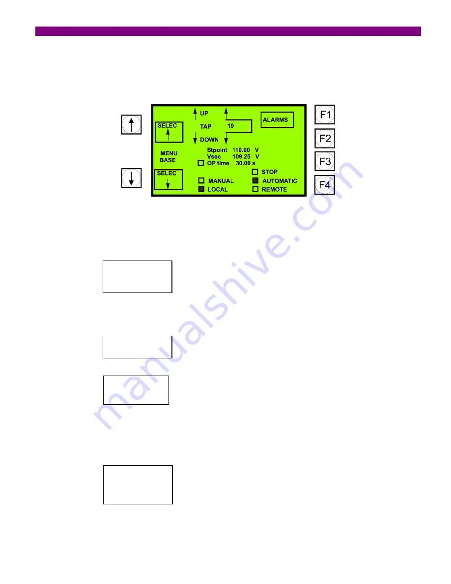
4.4 MAIN SCREEN
The following diagram shows the main screen. It represents the bay scheme or mimic.
When in stand-by, none of the elements in the display is selected. By pressing the keys on the left side, we can move
through the elements on which we can operate (tap-up, tap-down, stop, automatic, manual). When selected, the
element will be shadowed, and the F4 key will show which operation can be commanded.
OPERATE
F4
If we press the operation key, the relay will ask for confirmation or cancellation of the operation, as follows:
CANCEL
F1
CONFIRM
F2
If the operation is not performed, for example, because there is a programmed block that disables it, the display will
read:
OPERATION
FAILURE
Besides, in the main screen, instead of showing “
CANCEL
”, it will show “
MENU SELEC
”, to return to the initial menu
of the operation selection.
Summary of Contents for DTR GEK-106305A
Page 5: ...TABLE OF CONTENTS 4 DTR Digital Tap Changer Controller GE 106305A ...
Page 49: ...4 PROGRAMMING THE UNIT 48 DTR Digital Tap Changer Controller GE 106305A ...
Page 55: ...5 TECHNICAL CHARACTERISTICS 54 DTR Digital Tap Changer Controller GE 106305A ...
Page 71: ...8 INSTALLATION AND MAINTENANCE 70 DTR Digital Tap Changer Controller GE 106305A ...
Page 83: ...9 KEYPAD AND DISPLAY 82 DTR Digital Tap Changer Controller GE 106305A ...
Page 87: ...FIGURES 86 DTR Digital Tap Changer Controller GE 106305A FIGURE 3 PANEL MOUNTING DIAGRAM ...
Page 88: ...FIGURES GEK 106305A DTR Digital Tap Changer Controller 87 FIGURE 4 RS 232 CONNECTION ...
Page 89: ...FIGURES 88 DTR Digital Tap Changer Controller GE 106305A FIGURE 5 DIMENSIONS DIAGRAM ...
Page 90: ...FIGURES GEK 106305A DTR Digital Tap Changer Controller 89 FIGURE 6 FRONT VIEW ...
Page 91: ...FIGURES 90 DTR Digital Tap Changer Controller GE 106305A FIGURE 8 GENERIC REAR VIEW ...


