background image

31-5000276   Rev. 1

7

Installation Instructions

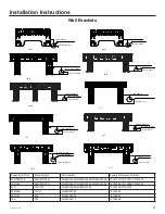
B.  Install the Mounting Plate

•   Remove plastic bag, tape, and mounting plate 

from the back of the indoor unit.

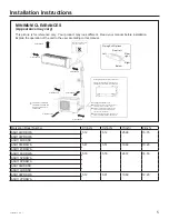
•   Place the mounting plate on the wall in the 

desired location taking into account the 

minimum clearances necessary for proper 

operation.

•   Using a level, verify that the mounting plate is 

horizontal and mark the screw locations.

•   Attach the mounting plate to the wall with the 

supplied screws. 

•   Wall anchors are supplied if not able to align all 

screw holes with studs.

•   Be sure that the mounting plate has been 

attached firmly and that applied weight is 

evenly distributed by each screw.  (At least 

one screw in wall stud, others can use wall 

anchors.)

•   The piping for the indoor unit may be routed to 

and from the unit in one of several directions:  

left, left rear, right, right rear, or right below.  

See Illustration on page 7.

•   Knockouts are provided on the unit case for 

Left, Right, and Right Below usage.

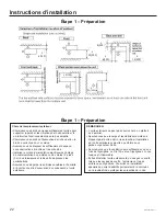
Step 2 - Installation of the Indoor Unit 

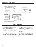
A.  Select the Indoor location:

•   Do not allow any heat or steam near the unit.

•   Select a location where there are no obstacles in 

front of the unit.

•   Make sure that condensate drainage can be 

conveniently routed away.

•   Do not install near a doorway.

•   Ensure that the space around the left and right 

of the unit is more than 4”. The unit should be 

installed as high on the wall as possible but allow 

a minimum of 4” from the ceiling. 

•   Use a stud finder to locate and mark stud locations 

for mounting and to prevent unnecessary damage 

to the wall.

•   Install in a location that is strong enough to 

withstand the full weight and vibration of the unit.

•   Leave enough space to allow access for routine 

maintenance.

•   Select a location that gives easy access to 

removing and cleaning air filters.

•   Install in a location that is 3 ft. or more away from 

other electrical appliances, such as televisions and 

audio devices.

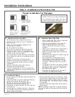
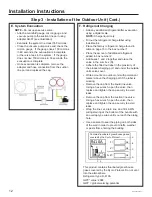
Proper Installation for Drainage

Set the unit on mount or pad using team lift.

Do not install the drain elbow if the unit is 

located in an area where freezing can occur.

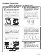
C.  Install the Tubing 

•   Measure and mark the location where the piping hole 

is to be drilled.  

•   Follow these steps to move the drain pipe if the pipe 

location will be on the left side of the unit.

1.  Remove the stopper in the left drain hole and 

knockout the molded plug inside the port.

2.  Transfer the corrugate drain hose from the right side 

to the left side.

3.  Insert stopper into right side drain port.  Using soap 

as a lubricant and a small screwdriver will allow for 

easier seating of the stopper.

•   Drill the lineset hole using a 2 1/4” hole saw.  Angle 

the drill with a downward pitch to the outside wall so 

that the outside wall hole will be at least a ¼” lower 

than the inside hole.  This allows for proper drainage 

of condensate.

•   Install the lineset hole flange at the hole opening on 

the inside wall.

NOTE:

 The flange is prescored.  It may be necessary 

to modify the flange to fit properly behind the wall unit 

housing.

Summary of Contents for ASH124CRDWA

Page 1: ...READ CAREFULLY KEEP THESE INSTRUCTIONS 31 5000276 Rev 2 01 20 GEA Ductless Single Zone with Highwall Indoor Unit Installation Instructions...

Page 2: ...s systems require that contractors and technicians use tools equipment and safety standards approved for use with this refrigerant DO NOT use equipment certified for R22 refrigerant only IMPORTANT SAF...

Page 3: ...to improper installation is not covered under the limited warranty For personal safety this system must be properly grounded Protective devices fuses or circuit breakers acceptable for installation ar...

Page 4: ...l R 410A flaring tool Hex wrench Hole saw 2 1 4 Insulation Refrigerant scale Level Manifold gauge set Measuring tape Micron gauge Mini split adapter 5 16 F to 1 4 M Nitrogen Pipe cutter PVC pipe optio...

Page 5: ...h 7 16 10mm bolts Use the mounting feet pads or vibration mats where noise transmission may be a concern Follow local code when mounting the unit on a wall rooftop or an area a ected by strong winds o...

Page 6: ...away from television and radio sets to prevent interference Ensure any moisture sensitive items are kept away from the condensate drain path of the OD unit NOTES OD unit cannot hang from a ceiling or...

Page 7: ...mum of 4 from the ceiling Use a stud finder to locate and mark stud locations for mounting and to prevent unnecessary damage to the wall Install in a location that is strong enough to withstand the fu...

Page 8: ...ith the top of the indoor unit closer to the wall hang the indoor unit on the upper hooks of the mounting plate Slide the unit slightly side to side to verify proper placement Rotate the lower portion...

Page 9: ...82in 124mm 2 1 4in 57mm 70 T 3 150in 80mm 1 85in 47mm 35 T 2 1 4in 57mm Capacity BTUh Bracket Style Part Number Factory Reference Number 07K 09K 12K 35N 35T 40N WJ65X23038 WJ65X23240 WJ65X23038 101012...

Page 10: ...is required by code Remove the cover plate of the outdoor unit to expose the terminal block connections B Electrical Connections for the Outdoor Unit WARNING RISK OF ELECTRIC SHOCK Could cause injury...

Page 11: ...rge the system with 150 psig of dry nitrogen using mini split adapter to connect the valve Check for leaks at the flare fittings using soap bubbles or another detection device If a leak is detected ma...

Page 12: ...nal refrigerant added in box number 2 Add boxes 1 and 2 together and place the value in the sum box D Adhere the filled out label in the proximity of the product charging port and under the outside un...

Page 13: ...ll the outdoor unit in a place where water can drain freely If the above conditions cannot be met contact GE Appliances for assistance Check Items for Test Run No gas leak from linesets Are the linese...

Page 14: ...efurbished compressor or a replacement for all or part of the unit at its sole discretion to your licensed HVAC technician installer For the product models listed on Attachment 1 the Product this Stan...

Page 15: ...states and provinces the longer terms for Limited Parts Warranty and the Limited Compressor Warranty apply The remedy provided in this warranty is exclusive and is granted in lieu of all other remedi...

Page 16: ...16 31 5000276 Rev 1 Printed in China...

Page 17: ...LIRE ATTENTIVEMENT CONSERVEZ CES INSTRUCTIONS Instructions d installation Zone simple sans conduit avec unit int rieure en hauteur 31 5000276 Rev 2 01 20 GEA...

Page 18: ...formez vous aupr s de l organisme responsable d en disposer Ces syst mes de climatisation R 410A exigent que les entrepreneurs et les techniciens utilisent des outils des quipements et des normes de s...

Page 19: ...t ce produit doit tre correctement mis la terre Les dispositifs de protection fusibles ou disjoncteurs admissibles pour l installation sont sp cifi s sur la plaque signal tique de chaque unit Si une r...

Page 20: ...Cl hexagonale Scie cloche 2 1 4 po Isolant Balance de r frig rant Niveau Manom tre de pression d admission d finir Ruban mesurer Microvacuom tre Adaptateur mini split 5 16 po F 1 4 po M Azote Coupe t...

Page 21: ...s vents Si le b timent est soumis des vibrations xez l unit en y ajoutant une carpette l preuve des vibrations Reportez vous au tableau ci dessous pour conna tre la position des pieds de montage et le...

Page 22: ...Assurez vous de garder les articles sensibles l humidit l cart du chemin d vacuation du condensat de l unit ext rieure REMARQUES L unit ext rieure ne peut pas s accrocher un plafond ou s empiler Assu...

Page 23: ...ligner tous les trous de vis sur les goujons V rifiez que la plaque de montage a t fix e solidement et que le poids est distribu uniform ment sur chaque vis Au moins une vis dans un montant mural les...

Page 24: ...ctuez les connexions chaque borne selon le sch ma de c blage Notez la couleur du fil chaque borne et assure vous que les fils connect s l unit ext rieure correspondent Assurez vous que chaque fil se t...

Page 25: ...K 36K 100N WJ65X22785 10103059 09K 12K 50F WJ65X25594 10104861 18K 70F WJ65X26113 10104864 35 N 1 84in 46mm 0 236in 6mm 2 1 4in 57mm 40 N 2 795in 71mm 0 472in 12mm 2 1 4in 57mm 4 961in 126 mm 1 417in...

Page 26: ...z le c blage de l alimentation lectrique et de l unit int rieure l aide d une bride de c ble de conduit sur le c t de l unit ext rieure pour le c ble 14 4 AWG et le c ble d alimentation lectrique l ai...

Page 27: ...servoir d azote muni d un r gulateur chargez le syst me 150 psig d azote sec en utilisant l adaptateur mini split pour raccorder le robinet V rifiez l absence de fuites aux raccords vas s l aide de b...

Page 28: ...e au tableau de la page 33 dans la case num ro 1 Inscrivez la quantit de frigorig ne additionnelle ajout e dans la case num ro 2 Additionnez les valeurs des cases 1 et 2 et placez le r sultat dans la...

Page 29: ...otection walls ODU Murs de protection Unit ext Unit ext Brise marine Mer ODU ODU Sea breeze Sea ODU Sea breeze Sea Unit ext Unit ext Unit ext Brise marine Brise marine Mer Mer tape 4 V rification fina...

Page 30: ...30 31 5000276 Rev 1 NOTES...

Page 31: ...installateur en chauffage ventilation et climatisation agr Cette Garantie limit e standard est attribu e l Acheteur initial du Produit pour les mod les num r s sous l Annexe 1 le Produit QUELLE EST L...

Page 32: ...gues de la Garantie limit e sur les pi ces et la Garantie limit e sur le compresseur qui s appliquent Le recours autoris dans cette garantie est exclusif et il est accord en remplacement de tout autre...

Page 33: ...LEA CUIDADOSAMENTE GUARDE ESTAS INSTRUCCIONES Instrucciones de instalaci n Unidad Interna para Pared Alta sin Conducto y de Zona nica 31 5000276 Rev 2 01 20 GEA...

Page 34: ...s consulte a la compa a a cargo del manejo de productos descartados Estos sistemas de acondicionadores de aire R 410A requieren que los contratistas y t cnicos usen herramientas equipos y est ndares d...

Page 35: ...eguridad personal este sistema deber estar correctamente conectado a tierra Los dispositivos de protecci n fusibles o disyuntores aceptables para la instalaci n aparecen especificados en la placa de c...

Page 36: ...R 410A Llave Hexagonal Sierra de Agujero de 2 1 4 Aislante Escala de refrigerante Nivel Calibrador de Colector conjunto Cinta de Medici n Medidor de Micrones Adaptador para Mini Split 5 16 H a 1 4 M...

Page 37: ...e 4 pulgadas m s de 4 pulgadas m s de 6 pulgadas m s de 6 pulgadas m s de 24 pulgadas Dimensiones de fijaci n al piso de la unidad de exterior Consulte la tabla a continuaci n para conocer las posicio...

Page 38: ...televisi n y radio a fin de evitar interferencias Aseg rese de que cualquier tem sensible a la humedad sea mantenido lejos del camino del drenaje condensado de la unidad de exterior NOTAS La unidad d...

Page 39: ...agujero del conjunto de cables con una sierra de agujero de 2 1 4 Angule el taladro con una inclinaci n descendente en relaci n a la pared exterior de modo que el agujero de la pared exterior est por...

Page 40: ...nnect 1 2 3 Blanco Negro Rojo Verde Colores Sugeridos 230 Volt Supply 1 to L1 2 to L2 Soportes del Amortiguador de Refuerzo placa de montaje E Monte la Unidad de Interior en la Placa de Montaje Ate la...

Page 41: ...0102740 30K 36K 100N WJ65X22785 10103059 09K 12K 50F WJ65X25594 10104861 18K 70F WJ65X26113 10104864 35 N 1 84in 46mm 0 236in 6mm 2 1 4in 57mm 40 N 2 795in 71mm 0 472in 12mm 2 1 4in 57mm 4 961in 126 m...

Page 42: ...es de la unidad de exterior Adhiera el codo de drenaje suministrado a la unidad de exterior Conecte la extensi n de la tuber a de acuerdo con lo requerido no suministrada Vea la ilustraci n NOTA El co...

Page 43: ...reads and cause a refrigerant leak Pipe Diameter Fastening torque Liquid side 6 35mm 1 4 18N m 13 3Ft lbs Liquid Gas side 9 52mm 3 8 42 N m 30 1Ft lbs Gas side 12 7mm 1 2 55N m 40 6Ft lbs Gas side 15...

Page 44: ...de carga de refrigerante usando tinta indeleble Coloque la carga de refrigerante de f brica que se encuentra en la casilla n mero 1 del gr fico de la p gina 51 Coloque la cantidad de refrigerante adi...

Page 45: ...La unidad de exterior deber ser instalada a por lo menos milla de distancia del agua salada incluyendo costas marinas y v as navegables interiores Si la unidad es instalada a entre y 5 millas de dista...

Page 46: ...eparado o el reemplazo de toda o parte de la unidad a su propia discreci n a su t cnico de instalaci n con licencia de HVAC Para los modelos de los productos que figuran en el Adjunto 1 el Producto es...

Page 47: ...ados para la Garant a Limitada de Piezas y la Garant a Limitada del Compresor La soluci n provista en esta garant a es exclusiva y es garantizada en lugar de todas las dem s soluciones Esta garant a n...

Page 48: ...Not Return This Product To The Store If you have a problem with this product please call 1 844 487 9443 for the name and telephone number of the nearest authorized service center DATED PROOF OF PURCH...

Reviews: