background image

Modifications 

Reserved 


   12 

OPM_ITS_USM_M06_M20_0US_V011  (09/2007) 


7.4   

Computer Network Security Recommendations


When configuring devices such as PC servers, clients, gateways, and Intelligent Electronic Devices (including UPS products equipped with 

data communications capabilities) to interconnect over existing LAN's or other IT infrastructure, it is necessary to take appropriate 

precautions to ensure the secure and stable operation of these systems and the data that resides on them: 
 

• 

For PC's running client and/or server applications, an antivirus solution should be installed and set to automatically update the 
program and virus definition files.    For operating systems such as Microsoft Windows XP, Automatic Update functionality should be 

enabled. 

• 

Unique usernames and passwords should be applied wherever such a feature is available, including but not limited to, operating 
systems, HMI application software, or configuration and control of gateways, firewalls, and Intelligent Electronic Devices.    Factory 

default passwords or blank passwords should always be changed prior to commissioning any system.   

• 

A VPN/Firewall appliance should be installed between the devices and the rest of the IT infrastructure to which they are connected 
(both Intranet and Internet).    As a minimum, these appliances should be configured to only permit communications between the 
devices being protected and the specific external systems, which are intended and authorized to communicate with them.


CAUTION 


Failure to take such preventative security measures could result in loss or misuse of data collected by 
these systems, and in some cases could permit unauthorized access to the control and settings 

functions of the devices being monitored.


8 -    Maintenance and Storage 

 
8.1   Maintenance


8.1.1.  Keep the UPS unit clean and vacuum the ventilation intake periodically. 

8.1.2.  Wipe with soft loose and damp cloth. 

8.1.3.  Check for loose and bad connections monthly. 
8.1.4.  Never leave the UPS unit on an uneven surface. 

8.1.5.  Position the unit to allow at least 10cm (4 inches) clearance between the rear panel and any obstruction such as walls. Keep 

UPS ventilation intake open and unobstructed. 

8.1.6.  Avoid direct sunlight, rain and high humidity. 

8.1.7.  Keep away from fire and extreme over-temperature locations. 

8.1.8.  Do not stack materials on top of the unit. 
8.1.9.  The UPS unit should not be exposed to corrosive air. 

8.1.10.  Normal operating temperature is 0 to 35°C


(32 to 95°F). 


8.2  

Storage Conditions


Store the UPS covered and upright in a cool and dry location, with its battery fully charged. Before storing, charge the UPS for at least 4 

(four) hours. Remove any accessories in the communication slot and disconnect any cables connected to the computer interface port to 

avoid unnecessary draining of the battery. 
 

8.3   

Extended Storage Conditions


8.2.1. Storage in an environment where the ambient temperature is -15 to +30°C (+5 to +86°F), charge the UPS‘s battery every 6 (six) 

months.  
8.2.2. Storage in an environment where the ambient temperature is +30 to +45°C (+86 to +113°F), charge the UPS‘s battery every 3 

(three) months.   


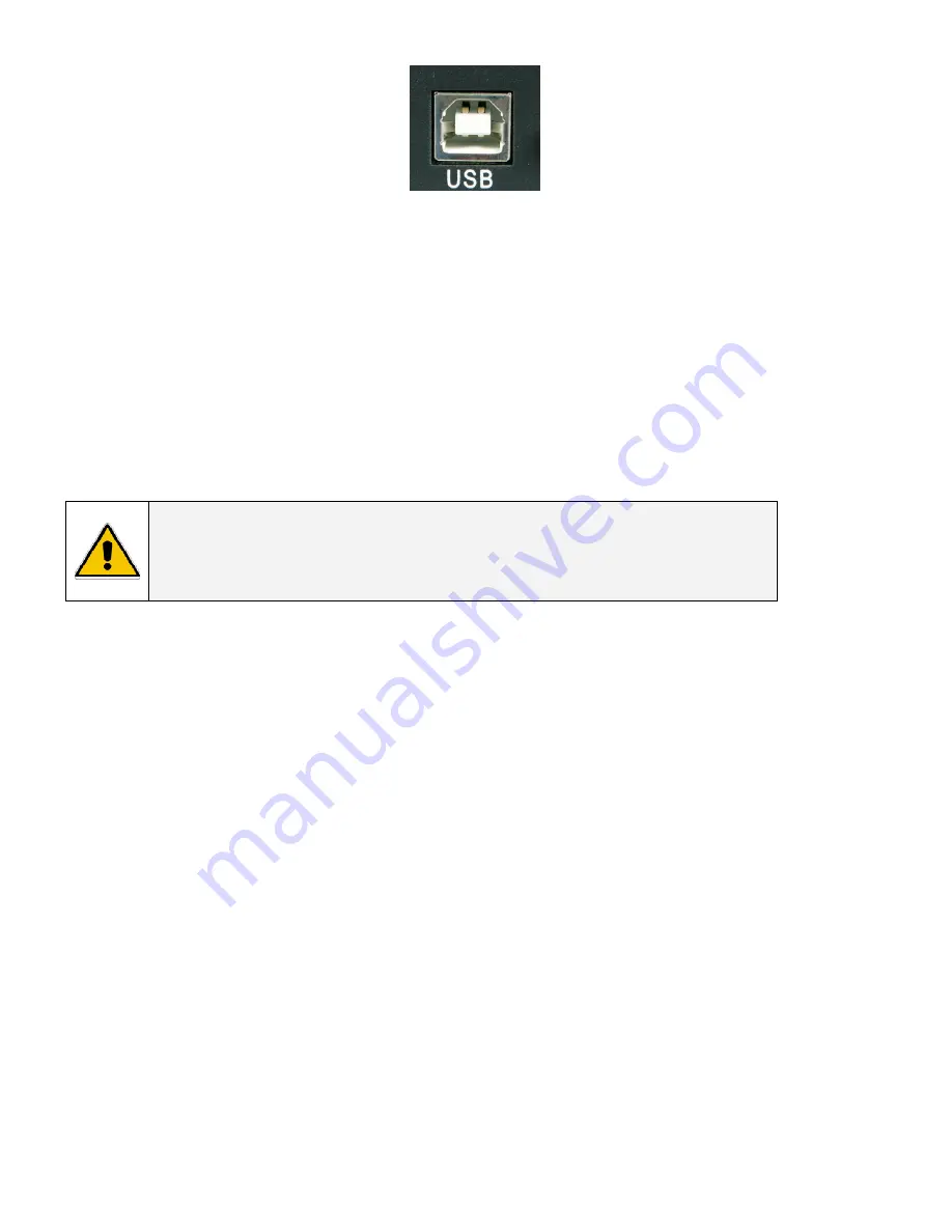
(Female Type “B” connector View) 

Summary of Contents for Amersham Imager 600

Page 1: ...al Digital Energy Uninterruptible Power Supply IT Series Line Interactive True Sine Wave UPS Tower Models 600 1000 1500 2000VA Rack Mount Models 600 1000 1500 2000VA GE Consumer Industrial Power Quali...

Page 2: ...lace for future reference General Electric Consumer Industrial All rights reserved reproduction without permission prohibited The content of this manual may be subject to change without prior notice n...

Page 3: ...3 Charge the battery 3 3 4 Connect to utility supply 3 3 5 Check the site wiring fault indicator 3 3 6 Advanced monitoring software 3 3 7 Rack mounting installation 4 Layout Control Panel 5 4 1 Front...

Page 4: ...k Security Recommendations 8 Maintenance and Storage 12 8 1 Maintenance 8 2 Storage Conditions 8 3 Extended Storage Conditions 9 Battery 13 9 1 Battery Life 9 2 Battery Rules 9 3 Safety precautions 9...

Page 5: ...ges Do not open the unit there are no user serviceable parts inside All maintenance and service work except replacement of the batteries should be performed by qualified service personnel After switch...

Page 6: ...ly even when UPS power switch is OFF Furthermore in order to save battery energy UPS can automatically turn the charger OFF under backup mode if none of the connected loads are operating The visual an...

Page 7: ...Contact the GE UPS Service Center for help at 800 637 1738 NOTE This warranty does not cover failures of the product which result from incorrect installation misuse alterations by persons other than a...

Page 8: ...components pinched wires and cables or not correctly inserted plugs This UPS is intended for use in a controlled indoor environment free of conductive contaminants and protected against animal intrusi...

Page 9: ...cording to applicable EMI EMC standards There is a possibility that interference to radio TV can occur in a particular installation If UPS causes interference to radio or television reception which ca...

Page 10: ...ile installing the new battery to avoid short circuits BUCK AVR VOLTAGE REDUCTION indicator AMBER LED The LED illuminates when the UPS is correcting a high utility voltage condition The loads receive...

Page 11: ...ector Telecom transfer IN OUT ports provide users to extend the RJ11 cable applications CAUTION To reduce the risk of fire use only No 26AWG or larger RJ11 telecommunication line cord OUTPUT POWER REC...

Page 12: ...relay signal to support for DOS WINDOWS and other operating systems USB Provided to support for DOS WINDOWS and other operating systems COMMUNICATION CARD INTERFACE SLOT used for optional SNMP commun...

Page 13: ...rms a self test function During the self test the UPS operates in back up mode Note During the self test the UPS briefly supplies the loads from battery input the on battery LED illuminates If the UPS...

Page 14: ...iminate the overload alarm 7 Software and Interface Port 7 1 Power Monitoring Software The Digital Energy IT Series UPS MONITORing software uses standard RS 232 interface or USB port to perform monito...

Page 15: ...face USB port configuration The USB computer interface port located on rear of UPS has the following characteristics Immediately after connecting the UPS through USB port to a PC a pop up message near...

Page 16: ...municate with them CAUTION Failure to take such preventative security measures could result in loss or misuse of data collected by these systems and in some cases could permit unauthorized access to t...

Page 17: ...be taken to avoid electric shock and burns caused by contacting battery terminals or shorting terminals during battery installation 9 2 12 Do not touch uninsulated battery terminals 9 2 13 The instal...

Page 18: ...2 batteries 1500VA 3 batteries 2000VA 4 batteries Please call your local GE representative for pricing and availability 9 5 Hot Swappable Battery Replacement Tower Procedure Step 1 Remove front cover...

Page 19: ...TS_USM_M06_M20_0US_V011 09 2007 600 1000VA 1500 2000VA Step 3 Remove inside battery cover plate 600 1000VA Unscrew metal cover plate Phillips head screws Put screws in a safe location for reconnection...

Page 20: ...Step 4 Carefully slide batteries out 600 1000VA Pull tabs attached to battery out toward front to remove batteries See diagram below 600 1000VA 1500 2000VA Pull tray to remove batteries See diagram be...

Page 21: ..._ITS_USM_M06_M20_0US_V011 09 2007 600 1000VA 1500 2000VA Disconnect Black wire Disconnect Red wire Continue to slide batteries out See diagrams below 1500 2000VA Step 6 Remove batteries from UPS case...

Page 22: ...Step 8 Connect Jumper wire s to the and of the new batteries as shown in diagrams above Step 9 Before inserting the batteries into the unit Connect the Black and Red Wire on the terminal as shown in...

Page 23: ...e Step 12 Install Metal Battery cover plate Install metal plate with Phillips head screws Step 13 Re Install Left front cover first by using the Phillips head screws Put the Right front cover on the R...

Page 24: ...Modifications Reserved 20 OPM_ITS_USM_M06_M20_0US_V011 09 2007 600VA 1000VA 1500 2000VA Step 3 Unscrew Left side panel by removing Phillips head screws See diagrams below 600VA 1000VA...

Page 25: ...00VA Step 4 Remove inside Battery cover plate Unscrew metal cover plate Phillips head screws Put screws in a safe location for reconnection See diagrams below 600VA 1000VA 1500 2000VA Step 5 Carefully...

Page 26: ...Modifications Reserved 22 OPM_ITS_USM_M06_M20_0US_V011 09 2007 600VA 1000VA 1500VA 2000VA Step 6 Disconnect Wires Disconnect Black and Red wires Continue to pull batteries out See diagrams below...

Page 27: ...Modifications Reserved 23 OPM_ITS_USM_M06_M20_0US_V011 09 2007 600VA 1000VA 1500VA 2000VA...

Page 28: ...Step 8 Install New Batteries using same battery type and layout as shown in diagrams above Step 9 Connect Jumper wire s to the and of the new batteries as shown in diagrams above Step 10 Before insert...

Page 29: ...ernal failure Contact the GE UPS Service Center for help at 800 637 1738 Alarm continues sounding Overload Remove some load Input circuit breaker on the rear panel has tripped Reset Input circuit brea...

Page 30: ...mperature F C 3 500 meters max elevation 32 95 F 0 35 C Humidity 0 95 humidity non condensing of Outlets NEMA 5 15R Tower 4 Rack Mount 4 Tower 4 Rack Mount 4 Tower 6 Rack Mount 4 Tower 6 Rack Mount 6...

Page 31: ...ch W x D x H Volume cu ft UPS0600ITSIT 13 80 30 42 14 80 32 63 265x550x340 10 4x21 7x13 4 1 75 UPS1000ITSIT 15 00 33 07 16 00 35 27 265x550x340 10 4x21 7x13 4 1 75 UPS1500ITSIT 25 00 55 12 27 00 59 52...

Reviews: