•
..
Power Circuit Breakers Types AK-2 -15 and AK-2/3-25 GEI -50299
alternate breaker presents a convenient method
of mechanically interlocking two or more breakers
to assure that no two breakers may be closed at
the same time.
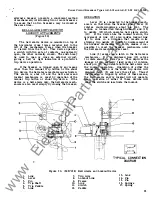
BELL ALARM SWITCH
LOCKOUT ATTACHMENTS
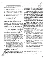
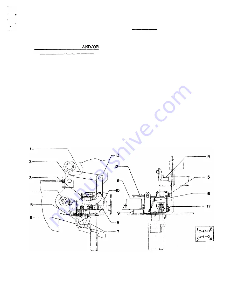
(Figure 30)
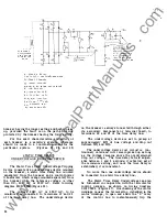
The bell alarm device is mounted on top of
the horizontal cross frame member just to the
left of the mechanism frame when the breaker
is viewed from the front. This device operates
a switch with two sets of contacts, one normally
open, the other normally closed. The switch may
be used to open or close an external circuit,
giving a bell or light indication of a protective
trip device operation.
If
the breaker is tripped open by any means
other than the manual trip button or the shunt
trip device, the bell alarm mechatiism is activated.
The alarm is shut off and the bell alarm and
lockout mechanism is reset by operation of the
manual trip button or shunt trip device.
If
the
device is a bell alarm only, the bell alarm mech
anism is also reset simply by closing the breaker.
4
OPERATION
Lever (2) is connected to the breaker mech
anism so that when the breaker opens lever (2)
rotates counterclockwise about pin (14).
The
motion is transmitted through links ( 1 ) and (13)
to paddle (12) which operates bell alarm switch
( 1 1 } .
If
the device has the lockout feature, the
movement of link (13) also causes lockout link
(8) to slide in a direction that results in its
striking trip paddle '5) which, by displacement of
the breaker mechanism trip latch, makes it im
possible to reset the breaker mechanism until
the bell alarm mechanism is reset.
Link (6) serves as a latch in the bell alarm
mechanism.
If
it is displaced, link (10) is free
to rotate about its lower pin. This deprives the
linkage of its normally fixed center of rotation
about pin (15) and defeats both the bell alarm and
the lockout operation.
Operation of either the
manual trip button or the shunt trip device will
displace latch (6) and have this effect. Thus
if
the breaker is tripped by either of these means,
the bell alarm and/or lockout will not operate.
Also, operation of either of these devices will
reset the switch and inactivate the lockout.
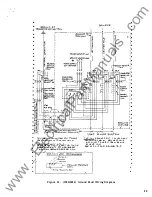
TYPICAL CONNECTION
DIAGRA M
Figure 30. (695C1 58) Bell Alarm anrl Lockout Device
1 . Link
2 . Lever
3. Pin
4. Trip Shaft
5 . Trip Paddle
6.
Link
7. Trip Arm
8.
Lockout Link
9.
Frame
10.
Link
1 1 . Switch
12 . Paddle
13. Link
14. Pin
1 5. Pin
1 6. Springs
1 7 . Spring
3 5
www
. ElectricalPartManuals
. com

