,.
..
,-
1
I
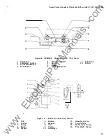
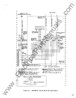
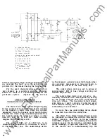
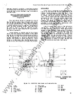
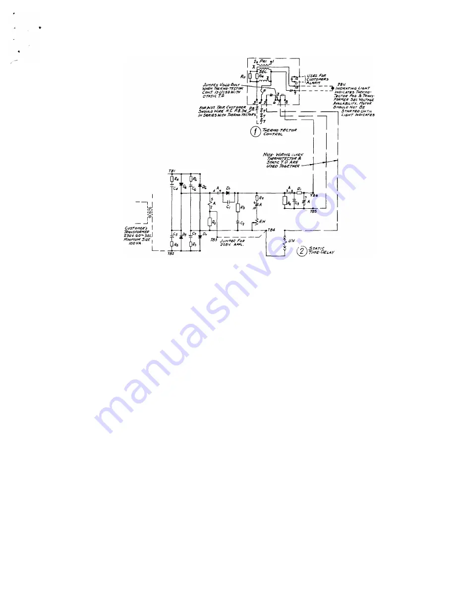
A· 25tJ 1/.0C REt..A.'I
C,,C4,C5., Ct.,C7 -
ltJ-v!'tttJ%
�00 wvoc
C2 - S!Ia-"f 35a WVIJC
C 3 - 1000-'lf 200 WVIJC
01,D�D5,D,,O]-
/N!I'O
Ra - 2756A 2ow t 5,..
RJI- o -25K 25W
R9 - -'oo.n. .3 W "t 5 1'.,
1(10,1?,1 -
sa-"- ;:sw.
�00 11'14 � 30°C
R, - 15 -" 2W !
311
R, - t5ooA
5W t 5%
R3 - 7S .Il. SW
!5%
R,J?5,f(,,f(r
10.n.
'kW.
F- I AMP LJV.s5 Fl.l:>£ TYP£ ,;f;G&
T· l#EI\'NO 'T"EC.TOR
x- 7J<,.,_,r:
/lsj?3avAv
- 24V SE�.
i!- 12 1/ A.c Rc.LA'f
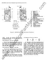
breaker through a normally closed
"Z"
contact
in series with the undervoltage device mounted
on the breaker.
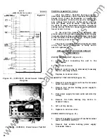
WARNING - Do not use bell set to check con
tinuity of bridge circuit in static time delay box,
only a volt-ohm meter or vacuum tube volt meter
should be used.
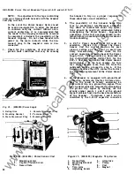
In the event the device fails to pick-up, the
following checks are recommended to determine
whether the magnetic device on the breaker or
the static time delay unit is the faulty component.
A.
B .
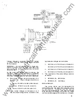
Check input voltages across terminals 1
&
2
on static box. These voltages should be as
follows :
1 . Device 177L3 1 6 G- 1 2- 2 08 or 230 volts A.C .
2 . Device 177L3 1 6 G- 14- 125 volts D.C.
3 . Device 1 77L3 1 6 G- 1 5 - 2 50 volts D.C .
Check output voltages on terminals 4
&
5
with the under voltage device connected. The
approximate voltages are as follows:
1 . 2 0 8 Volt A . C. 1 77L3 1 6 G- 1 2 - l lO volts D.C .
230 Volt A.C. 177L3 1 6 G- 12- 120 volts D .C .
2 . 1 2 5 Volt D.C. 177L3 1 6 G- 14 5 0 volts D . C .
3 . 250 Volt D.C. 1 77L3 1 6 G- 1 5- 100 volts D.C.
c.
The resistance of the under-voltage coils are
as follows :
1 .
2 .
62 75080 G-59 - 1 830 Ohms.
6275081 G-61 - 440 Ohms .
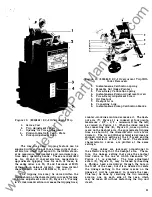
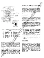
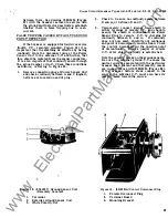
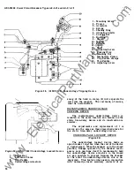
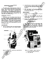
REPLACEMENT
The entire device may be dismounted by
disconnecting the coil leads and removing screw
( 1 ) and nuts 1 6 .
Normally, only the coil ( 1 2 )
will ever need replacement. This may b e removed
from the device by taking out screws ( 1 1 ) which
will free both the magnet ( 1 0) and the coil. Straight-
33
www
. ElectricalPartManuals
. com


