Power Circuit Breakers Types AK-2-15 and AK-2/3-25 GEI-50299
6. If
the breaker is manually operated, and has
no auxiliary switch, it is now free to be lifted
clear of the breaker.
If
it has an auxiliary
switch, this may be disconnected from the
mechanism as described under "Auxiliary
Switch - Replacement, elsewhere in these
instructions.
7. If
the breaker is electrically operated, it will
be necessary to disconnect the mechanism from
the solenoid armature.
In
order to do this,
raise the mechanism as far as the travel of the
armature will permit and remove the screw
which binds together the two extensions
of
the
armature. After this is removed, the armature
extensions must be spread apart to release
them from the link connecting with the mech
anism.
This can be done by threading a
#10-32
screw at least
1-3/4
inches long into
the top hole of the armature extension. This
hole is just above the one from which the
binding screw has been removed. As the end
of the screw butts against the far extension,
the two extensions will be spread open, re
leasing the mechanism
link
.
8.
The replacement mechanism may be installed
by reversing the order of procedure for dis
assembly. After reassembly, check the opera
tion of the breaker and, if necessary, adjust
the latch engagement.
REMOVAL OF FRONT ESCUTCHEON
OF MANUAL BREAKERS
1.
Remove set screw fastening the plastic handle
to steel operating shaft and remove the oper
ating
2.
Open and remove annealed (soft) retainer and
two flat washers from shaft.
3.
Remove four screws from flange of escutcheon
If
the breaker is a drawout type, two small
round head screws must also be removed from
the bottom edge of the escutcheon.
4.
Push steel operating shaft through escutcheon
bushing.
5.
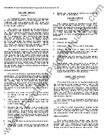
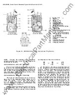
Remove handle reset spring
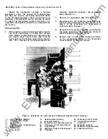
(8)
Figure
6,
and
escutcheon is free of breaker.
6 .
Handle and escutcheon assembly can be as
sembled most easily by exactly reversing the
procedure for disassembly. In replacing the
escutcheon it may be necessary to use pliers
to pull the operating shaft fully into the
escutcheon in order to have space enough to
replace the flat washers and the soft retainer.
The latter may be closed on its groove in
the shaft by ordinary gas pliers. After re
placement,
check operation of breaker.
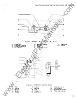
AUXILIARY SWITCH
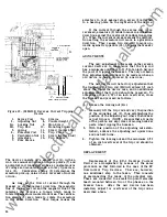
The auxiliary switch is mounted on the left
side of the operating mechanism frame. Its opera
ting shaft is linked to the output crank
of
the breaker
mechanism.
Through a cam arrangement, the
operating shaft of the switch controls the open and
closed positions of the individual contact pairs.
Each stage of the switch, which is usually two-stage
or five-stage, contains one "a" and one
''b"
set
of contacts.
An
"a" pair of contacts is always in
the same position as the main breaker contacts .
That is, open when the breaker contacts are open,
and closed when the breaker contacts are closed.
Just the oposite is true of the "b" contacts. The
terminals of the switch are covered by a sheet of
insulating material held in place by two screws
fastened along its left edge. When this is removed,
the terminals are exposed. The upper pairs of
terminals are those which connect to "a" switches.
The lower terminals connect to
''b"
switches.
REPLACEMENT
1.
Remove auxiliary switch cover.
2.
Disconnect leads to switch terminals.
3.
Remove two screws which fasten switch to
side
of
mechanism frame.
4.
Remove switch by moving towards left.
5.
Before mounting replacement switch, turn the
crank end
of the switch operating shaft in
position to engage the hole in the link con
necting with with the breaker mechanism.
Be sure the bearing washer is in place between
the mechanism
link
and the switch operating
shaft.
6.
Complete mounting by following disassembly
steps in reverse order.
ELECTRICAL CONTROL COMPONENTS
These consist
of
the following:
1.
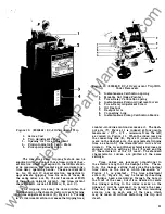
Closing solenoid
2. "X"
contactor (relay)
3 .
"Y"
permissive relay
4.
Cut-off switch
5.
Closing switch
6.
Shunt-trip device
The last two of these components may or
may not be present in the control arrangement.
15
www
. ElectricalPartManuals
. com


