3 SETUP AND USE
g
GE Power Management
50
3$*(
'(6&5,37,21
5
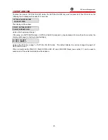
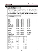
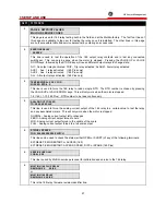
PAGE 5: SETPOINT VALUES
SYSTEM CONFIGURATION
This page is used to configure the 169 relay to exactly match the motor and motor system being
protected. Various special features can be selected, defeated, or adjusted in this page of setpoints.
5
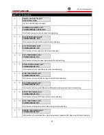
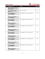
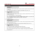
NORMAL RUN DISPLAY SHOWS
LINE = LINE XX
This code determines the line of the selected page in ACTUAL VALUES MODE to which the display will
return if no key is pressed for more than four minutes and no trips or alarms are present:
1-40 - line number in selected page (see Table 3-2); Factory Value = 2
5
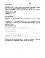
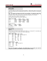
NORMAL RUN DISPLAY SHOWS
PAGE = PAGE XX
This code determines the page in ACTUAL VALUES mode to which the display will return if no key is
pressed for more than four minutes and no trips or alarms are present:
1 or 7 - page 1 (see Table 3-2)
2 or 8 - page 2
3 or 9 - page 3
4 or 10 - page 4
5 - page 5
6 - page 6
Factory Value = 1
5
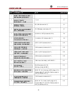
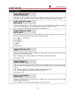
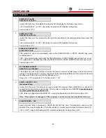
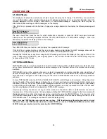
DEFEAT NO SENSOR ALARM?
XXX
This code is used to enable or defeat the Broken RTD Sensor Alarm. This alarm will only become active
for open circuit RTDs chosen for use:
YES - RTD Broken Sensor Alarm defeated; NO - RTD Broken Sensor Alarm enabled.
Factory Value = YES
5
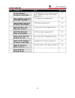
DEFEAT RTD INPUT TO
THERMAL MEMORY ? XXX
This code is used to enable or defeat the thermal memory RTD bias feature of the relay (see section
3.20). With this feature defeated the effect of the stator RTD temperature is not included in the thermal
memory:
YES - RTD bias defeated (RTD temperature does not affect thermal memory);
NO - RTD bias enabled (thermal memory reduced as per figure 3-4)
Factory Value = YES
5
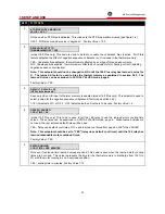
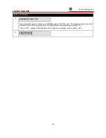
RTD BIAS CURVE MINIMUM
VALUE = XXX C
Not seen when RTD input to thermal memory is defeated. This code is used to set the RTD bias
minimum value (see figure 3-4):
0-200 - RTD bias curve minimum value in degrees C; Factory Value = 90
Summary of Contents for 169
Page 12: ......
Page 14: ...2 INSTALLATION g GE Power Management 8 Figure 2 2 CT Dimensions ...
Page 17: ...2 INSTALLATION g GE Power Management 11 Figure 2 4 Relay Wiring Diagram AC control power ...
Page 19: ...2 INSTALLATION g GE Power Management 13 Figure 2 6 Relay Wiring Diagram Two Phase CTs ...
Page 20: ...2 INSTALLATION g GE Power Management 14 Figure 2 7 Relay Wiring Diagram DC Control Power ...
Page 28: ...2 INSTALLATION g GE Power Management 22 Figure 2 10 169 Drawout Relay Physical Dimensions ...
Page 29: ...2 INSTALLATION g GE Power Management 23 Figure 2 11 169 Drawout Relay Mounting ...
Page 31: ...3 SETUP AND USE g GE Power Management 25 Figure 3 1 Front Panel Controls and Indicators ...
Page 73: ...3 SETUP AND USE g GE Power Management 67 Figure 3 2 Standard Overload Curves ...
Page 74: ...3 SETUP AND USE g GE Power Management 68 A B Figure 3 3 Custom Curve Examples ...
Page 88: ...5 THEORY OF OPERATION g GE Power Management 82 Figure 5 1 Hardware Block Diagram ...
Page 90: ...5 THEORY OF OPERATION g GE Power Management 84 Figure 5 2 Firmware Block Diagram ...

