background image

3 SETUP AND USE

g

GE Power Management

36

3$*( /,1( '(6&5,37,21

4

1

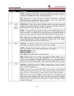
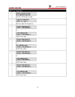
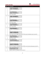
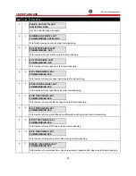
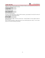
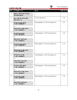
PAGE 4: ACTUAL VALUES
STATISTICAL DATA

ACTUAL VALUES page 4 header.

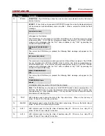
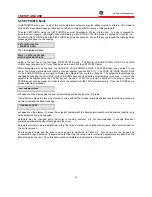
4

2

RUNNING HRS SINCE LAST
COMMISSIONING  XXXXX HRS

Total motor running hours since last commissioning.

4

3

# OF STARTS SINCE LAST
COMMISSIONING   XXX

Total number of motor starts since last commissioning.

4

4

# OF TRIPS SINCE LAST
COMMISSIONING  XXX

Total number of relay trips since last commissioning.

4

5

# O/L TRIPS SINCE LAST
COMMISSIONING XXX

Total number of relay overload trips since last commissioning.

4

6

# RAPID TRIPS SINCE LAST
COMMISSIONING XXX

Total number of relay rapid trips since last commissioning.

4

7

# U/B TRIPS SINCE LAST
COMMISSIONING XXX

Total number of relay unbalance trips since last commissioning.

4

8

# G/F TRIPS SINCE LAST
COMMISSIONING XXX

Total number of relay ground fault and differential input trips since last commissioning.

4

9

# RTD TRIPS SINCE LAST
COMMISSIONING XXX

Total number of relay RTD trips since last commissioning.

4

10

# S/C TRIPS SINCE LAST
COMMISSIONING XXX

Total number of relay short circuit trips since last commissioning.

4

11

#START TRIPS SINCE LAST
COMMISSIONING XXX

Total number of acceleration time, phase reversal and speed switch trips since last commissioning.

Summary of Contents for 169

Page 1: ...5 Anderson Avenue Markham Ontario L6E 1B3 Tel 905 294 6222 Fax 905 294 8512 www GEindustrial com pm 169 MOTOR MANAGEMENT RELAY Instruction Manual Software Rev 169 E7 5 Manual P N 1601 0003 A4 Copyright 2000 GE Power Management ...

Page 2: ...E2 E3 10 14 86 M17 07 87 E4 Rev E4 preliminary 7 17 87 M05 08 87 E4 Rev E4 8 5 87 M02 11 87 E4 Rev E4 D O hardware rev 11 2 87 M04 11 87 E4 Rev E4 11 4 87 M22 01 89 E5 Rev E5 1 22 89 M01 02 90 E5 Rev E5 1 2 90 M23 02 90 E6 Rev E6 2 23 90 M18 09 91 E7 Rev 169 E7 0 9 18 91 M30 10 91 E7 1 Rev 169 E7 1 10 30 91 M02 12 91 E7 2 Rev 169 E7 2 12 2 91 1601 0003 A1 Rev 169 E7 2 10 12 93 1601 0003 A2 Rev 169...

Page 3: ...Emergency Restart Terminals 18 2 13 External Reset Terminals 18 2 14 Analog Output Terminals 18 2 15 Differential Relay Terminals 169 Plus 19 2 16 Speed Switch Terminals 169 Plus 19 2 17 Programming Access Terminals 19 2 18 RS 422 Serial Communications Terminals 169 Plus 19 2 19 Display Adjustment 20 2 20 Front Panel Faceplate 20 2 21 Spare Input Terminals 169 Plus 20 2 22 169 Drawout Relay 21 3 1...

Page 4: ...Emergency Restart 71 3 22 Resetting The 169 Relay 71 3 23 169 Relay Self Test 72 3 24 Statistical Data Features 72 3 25 Factory Setpoints 73 4 1 Primary Injection Testing 76 4 2 Secondary Injection Testing 76 4 3 Phase Current Input Functions 76 4 4 Ground Fault Current Functions 79 4 5 RTD Measurement Tests 79 4 6 Power Failure Testing 79 4 7 Analog Current Output 80 4 8 Routine Maintenance Verif...

Page 5: ...Table 3 1 Controls and Indicators 26 Table 3 1 Controls and Indicators 31 Table 3 3 SETPOINTS 42 Table 3 5 Standard Overload Curve Trip Times in seconds 66 Table 3 6 PRE STORED FACTORY SETPOINTS 169 SETPOINT PAGES 1 3 74 Table 3 7 Preset Factory Relay Configurations and Functions 75 Table 4 1 RTD Resistance vs Temperature 79 ...

Page 6: ...complete accurate protection for industrial motors and their associated mechanical systems The 169 offers a wide range of protection monitoring and diagnostic features in a single integrated package All of the relay setpoints may be programmed in the field using a simple 12 position keypad and 48 character alphanumeric display A built in HELP function can instruct the user on the proper function o...

Page 7: ...ut relay becomes active the 169 will display the cause of the trip and if applicable the lock out time remaining Pre trip values of motor current unbalance ground fault current and maximum stator RTD temperature are stored by the 169 and may be recalled using the keypad The correct operation of the Multilin 169 relay is continually checked by a built in firmware self test routine If any part of th...

Page 8: ...ons The many features of the 169 make it an ideal choice for a wide range of motor protection applications Versatile features and controls allow the relay to protect associated mechanical equipment as well as the motor The 169 should be considered for the following and other typical uses 1 Protection of motors and equipment from operator abuse 2 Protection of personnel from shock hazards due to wi...

Page 9: ... setpoint 5 Amp secondary CT 0 3 amps primary 2000 1 CT Overload Curves trip time accuracy 1 sec up to 13 sec 8 of trip time over 13 sec detection level 1 of primary CT amps Unbalance display accuracy 2 percentage points of true negative sequence unbalance In Ip Relay Lock out Time accuracy 1 minute with control power applied 20 of total lock out time with no control power applied Trip Alarm Delay...

Page 10: ...m permissible load 5 VDC 100 mA NOTE AC inductive load PF 0 4 DC inductive load L R 7 msec Analog Current Output 4 20 mA standard output 4 20 mA 0 20 mA 0 1 mA maximum load resistance 300 Ω 300 Ω 2000 Ω maximum output saturation 20 2 mA 20 2 mA 1 01 mA accuracy 1 of full scale reading polarity terminal 58 must be at ground potential ie output is not isolated Control Power AC nominal 120 VAC range ...

Page 11: ...5 amp input less than 0 50 VA at rated load 2000 1 input can be driven by GE Power Management 2000 1 CT Running Hours Counter accuracy 1 Note It is recommended that all 169 relays be powered up at least once per year to avoid deterioration of electrolytic capacitors in the power supply Due to updating technology specifications may be improved without notice ...

Page 12: ......

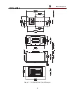
Page 13: ... indicators located on the front panel The physical dimensions of the 169 unit are given in Figure 2 1 Multilin also provides phase and ground fault CTs if required Dimensions for these are shown in Figure 2 2 Note Dimensions of Figure 2 2 are for 100 5 to 1000 5 phase CT s for the dimensions of 50 5 and 75 5 CT s consult factory Figure 2 1 Physical Dimensions ...

Page 14: ...2 INSTALLATION g GE Power Management 8 Figure 2 2 CT Dimensions ...

Page 15: ... is mounted as shown in Figure 2 3 Four washers and 10 32 X 3 8 mounting screws are provided Although the 169 circuitry is internally shielded to minimize noise pickup and interference the relay should be placed away from high current conductors or sources of strong magnetic fields Connections to the relay are made through terminal blocks and CTs located on the rear of the unit Figure 2 3 Relay Mo...

Page 16: ...ower down state Figures 2 4 2 6 2 7 show output relay contacts with power applied no trips or alarms Factory Configurations i e TRIP fail safe ALARM non fail safe AUX 1 non fail safe AUX 2 fail safe See Figure 2 5 for a complete list of all possible output relay contact states See page 62 for a description of the RELAY FAILSAFE CODE Table 2 1 169 External Connections Inputs Supply Power L G N Phas...

Page 17: ...2 INSTALLATION g GE Power Management 11 Figure 2 4 Relay Wiring Diagram AC control power ...

Page 18: ...WARNING In locations where system voltage disturbances cause voltage levels to dip below the range specified in specifications 1 5 any relay contact programmed failsafe may change state To avoid tripping the motor in this case trip relay contacts should be programmed non failsafe ...

Page 19: ...2 INSTALLATION g GE Power Management 13 Figure 2 6 Relay Wiring Diagram Two Phase CTs ...

Page 20: ...2 INSTALLATION g GE Power Management 14 Figure 2 7 Relay Wiring Diagram DC Control Power ...

Page 21: ... is energized Power is applied at terminals 41 42 and 43 which is a terminal block having 6 screws NOTE Chassis ground terminal 42 must be connected directly to the dedicated cubicle ground conductor to prevent transients from damaging the 169 169 Plus resulting from changes in ground potential within the cubicle AC VOLTAGE SELECTION SWITCH A100 PC BOARD Figure 2 8 AC Voltage Selection 120 240 VAC...

Page 22: ... condition will cause the relay contacts to go to their power down state Thus in order to cause a trip on loss of power to the 169 output relays should be programmed as fail safe The Trip relay cannot be reset if a lock out is in effect Lock out time will be adhered to regardless of whether control power is present or not The Trip relay can be programmed to activate on any combination of the follo...

Page 23: ... 1 non fail safe AUX 2 fail safe See Figure 2 5 for a list of all possible contact states 2 11 RTD Sensor Connections Up to six resistance temperature detectors RTDs may be used for motor stator temperature monitoring The remaining RTD inputs may be used for motor and load bearing or other temperature monitoring functions All RTDs must be of the same type RTD 8 RTD 10 on the 169 Plus may be used t...

Page 24: ...ich can accommodate up to 12 AWG multi strand wire 2 13 External Reset Terminals An external reset switch which operates similarly to the keypad RESET key see section 3 1 can be connected to terminals 56 and 57 for remote reset operation The switch should have normally open contacts Upon closure of these contacts the relay will be reset This external reset is normally equivalent to pressing the ke...

Page 25: ...e a new setpoint value the message ILLEGAL ACCESS will appear on the display and the previous setpoint will remain intact In this way all of the programmed setpoints will remain secure and tamperproof Alternatively these terminals can be wired to an external keyswitch to permit setpoint programming upon closure of the switch A twisted pair of wires should be used for connection to an external swit...

Page 26: ...ill not be possible In addition damage to the 169 Plus may result Figure 2 9 Serial Communication Link Wiring 2 19 Display Adjustment Once the 169 relay has been installed and input power applied the contrast of the LCD display may have to be adjusted This adjustment has been made at the factory for average lighting conditions and a standard viewing angle but can be changed to optimize the display...

Page 27: ...AY REMOVAL Open the hinged door Next remove the two ten finger connecting plugs making sure the top one is removed first Swivel the cradle to case hinged levers at each end of the 169 cradle assembly and slide the assembly out of the case RELAY INSTALLATION Slide the 169 cradle assembly completely into the case Swivel the hinged levers in to lock the 169 cradle assembly into the drawout case Insta...

Page 28: ...2 INSTALLATION g GE Power Management 22 Figure 2 10 169 Drawout Relay Physical Dimensions ...

Page 29: ...2 INSTALLATION g GE Power Management 23 Figure 2 11 169 Drawout Relay Mounting ...

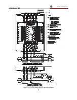
Page 30: ...2 INSTALLATION g GE Power Management 24 Figure 2 12 169 Plus Drawout Relay Typical Wiring Diagram ...

Page 31: ...3 SETUP AND USE g GE Power Management 25 Figure 3 1 Front Panel Controls and Indicators ...

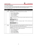
Page 32: ...4 Statistical Data page 5 Pre trip Data page 6 Learned Parameters 1 ACTUAL VALUES EFFECT Pressing this key will put the relay into ACTUAL VALUES mode The flash message ACTUAL VALUES HAS SIX PAGES OF DATA will be displayed for 2 seconds The beginning of page 1 of ACTUAL VALUES mode will then be shown PAGE 1 ACTUAL VALUES PHASE CURRENT DATA USE This key can be pressed at any time in any mode to view...

Page 33: ... HELP again for details will be displayed To obtain information on the function of a particular key the key must be pressed To obtain information on the previously displayed ACTUAL VALUES SETPOINTS or TRIP ALARM message the HELP key should be pressed again If this key is pressed with any other message shown on the display only information on the previous line will be available 3 HELP USE This key ...

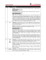
Page 34: ...ed the previous value will still be in effect FUNCTION The RESET key allows the user to reset the 169 after any of the latched output relays have become active so that a motor start can be attempted EFFECT Pressing this key will reset i e return to an inactive state any of the active output relay contacts if motor conditions allow see below The message RESET NOT POSSIBLE Condition still present wi...

Page 35: ... To do this the following message from page 4 of ACTUAL VALUES mode must be displayed after the NO value is altered to say YES by pressing the VALUE UP VALUE DOWN key START COMMISSIONING YES Then when the STORE key is pressed the following flash message will appear on the display COMMISSIONING data cleared All statistical data see section 3 24 will then be cleared USE The STORE key can be used onl...

Page 36: ...The other display modes can be entered using the ACTUAL VALUES SET POINTS or HELP keys see section 3 1 The ACTUAL VALUES and SETPOINTS modes are based on a book like system of pages and lines One line from any page may be displayed at any given time To turn a page the PAGE UP and PAGE DOWN keys are used To scan the lines on a page the LINE UP and LINE DOWN keys are used In the HELP and TRIP ALARM ...

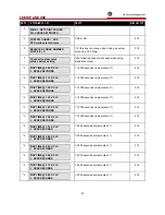
Page 37: ...during a motor start 1 3 I1 XXXX I2 XXXX I3 XXXX AMPS Motor phase current data becomes RUN when motor is running 1 4 I 3 ph avg XXXX AMPS Max Stator RTD XXX C Average of 3 phase currents Maximum of 6 stator RTDs 1 5 UNBALANCE RATIO In Ip U B XXX PERCENT Ratio of negative to positive sequence currents 1 6 GROUND FAULT CURRENT G F XX X AMPS Actual ground fault current 1 7 END OF PAGE ONE ACTUAL VALU...

Page 38: ...2 3 STATOR TEMPERATURE RTD 1 XXX DEGREES C or RTD TEMPERATURE RTD 1 XXX DEGREES C RTD 1 temperature 2 4 STATOR TEMPERATURE RTD 2 XXX DEGREES C or RTD TEMPERATURE RTD 2 XXX DEGREES C RTD 2 temperature 2 5 STATOR TEMPERATURE RTD 3 XXX DEGREES C or RTD TEMPERATURE RTD 3 XXX DEGREES RTD 3 temperature 2 6 STATOR TEMPERATURE RTD 4 XXX DEGREES C or RTD TEMPERATURE RTD 4 XXX DEGREES C RTD 4 temperature ...

Page 39: ... temperature 2 10 RTD TEMPERATURE RTD 8 XXX DEGREES C or AMBIENT TEMPERATURE RTD 8 XXX DEGREES C RTD 8 temperature Ambient seen when RTD 8 is used for ambient sensing on model 169 2 11 RTD TEMPERATURE RTD 9 XXX DEGREES C RTD 9 temperature 2 12 RTD TEMPERATURE RTD 10 XXX DEGREES C or AMBIENT TEMPERATURE RTD 10 XXX DEGREES C RTD 10 temperature Ambient seen when RTD 10 is used for ambient sensing on ...

Page 40: ...ESS XXX C Maximum RTD 8 temperature since last access 2 16 MAXIMUM RTD 9 TEMP SINCE LAST ACCESS XXX C Maximum RTD 9 temperature since last access 2 17 MAX RTD 10 TEMP SINCE LAST ACCESS XXX C Maximum RTD 10 temperature since last access 2 18 CLEAR LAST ACCESS DATA XXX Used to clear the data in the last 5 lines see section 3 1 STORE key 2 19 END OF PAGE TWO ACTUAL VALUES Last line of page 2 ...

Page 41: ...TIME TO TRIP XXX SECONDS Estimated time to overload trip under present conditions seen only during overloads 3 3 MOTOR LOAD AS A PERCENT FULL LOAD XXX PERCENT Actual motor current as a percentage of full load 3 4 THERMAL CAPACITY USED XXX PERCENT Percentage of motor thermal capacity used 3 5 END OF PAGE THREE ACTUAL VALUES Last line of page 3 ...

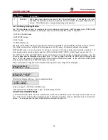
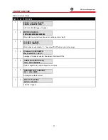
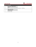
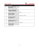
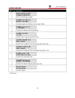
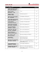
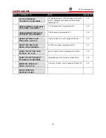
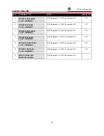
Page 42: ... commissioning 4 6 RAPID TRIPS SINCE LAST COMMISSIONING XXX Total number of relay rapid trips since last commissioning 4 7 U B TRIPS SINCE LAST COMMISSIONING XXX Total number of relay unbalance trips since last commissioning 4 8 G F TRIPS SINCE LAST COMMISSIONING XXX Total number of relay ground fault and differential input trips since last commissioning 4 9 RTD TRIPS SINCE LAST COMMISSIONING XXX ...

Page 43: ...P AND USE g GE Power Management 37 3 1 6 5 37 21 4 12 START NEW COMMISSIONING XXX Used to clear the data in the last 10 lines see section 3 1 STORE key 4 13 END OF PAGE FOUR ACTUAL VALUES Last line of page 4 ...

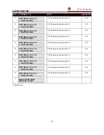
Page 44: ...ase current prior to last relay trip 5 3 PRE TRIP U B RATIO In Ip XXX PERCENT Ratio of negative to positive sequence currents prior to last relay trip 5 4 PRE TRIP G F CURRENT G F XXX AMPS Ground fault current prior to last relay trip 5 5 PRE TRIP MAX STATOR RTD RTD X XXX C Maximum stator RTD temperature prior to last relay trip 5 6 END OF PAGE FIVE ACTUAL VALUES Last line of page 5 ...

Page 45: ...6 4 LEARNED K FACTOR K XX X Learned value of negative sequence K factor 6 5 LEARNED RUNNING COOL TIME XXX MIN Learned motor cooling time with motor running see section 3 20 6 6 LEARNED STOPPED COOL TIME XXX MIN Learned motor cooling time with motor stopped see section 3 20 6 7 LEARNED ACCEL TIME ACCEL TIME XX X SEC Learned motor acceleration time 6 8 LEARNED Start Capacity required XX PERCENT Lear...

Page 46: ...TA which is the beginning of page 1 If the relay is in SETPOINTS mode or ACTUAL VALUES mode and no key is pressed for more than four minutes the display will change to factory default settings I1 XXX I2 XXX I3 XXX AMPS which is the third line in page 1 of ACTUAL VALUES mode This default display line can be changed in page 5 of SETPOINTS mode When in this mode the PAGE UP PAGE DOWN LINE UP and LINE...

Page 47: ...hemselves are changed by pressing the VALUE UP or VALUE DOWN keys until the desired setpoint value is reached To return the setpoint to its original value the CLEAR key can be used When the setpoint is adjusted to its proper value the STORE key should be pressed in order to store the setpoint into the 169 s internal memory Once the STORE key is pressed the flash message new setpoint stored will ap...

Page 48: ...TIME DELAY TIME DELAY XXX SEC 3 255 seconds increments of 1 3 10 1 UNBALANCE TRIP LEVEL U B TRIP XX PERCENT 4 30 or OFF increments of 1 3 10 1 U B TRIP TIME DELAY U B DELAY XXX SECONDS 3 255 seconds increments of 1 3 10 1 G F CT RATIO 5 XXX NO indicates 2000 1 YES 5 amp secondary or NO 2000 1 3 11 1 G F CT RATIO G F CT XXX 5 50 250 increments of 50 Not seen if ratio is 2000 1 3 11 1 GROUND FAULT A...

Page 49: ...C DELAY XXX SECONDS 1 255 seconds increments of 1 3 12 1 RAPID TRIP MECH JAM TRIP LEVEL X X X FLC 1 5xFLC 4 5xFLC or OFF steps of 0 5xFLC 3 13 1 RAPID TRIP TIME DELAY DELAY XXX X SECONDS 0 5 125 0 seconds increments of 0 5 3 13 1 SHORT CIRCUIT TRIP LEVEL S C TRIP XX X FLC 4xFLC 12xFLC or OFF increments of 1xFLC 3 14 1 SHORT CIRCUIT TIME DELAY S C DELAY XX X SECONDS Instantaneous or 0 5 20 5 sec st...

Page 50: ...RIP LEVEL XXX DEGREES C 0 200 degrees C or OFF increments of 1 3 16 2 RTD 2 ALARM LEVEL XXX DEGREES C or STATOR 2 ALARM LEVEL XXX DEGREES C 0 200 degrees C or OFF increments of 1 3 16 2 RTD 2 TRIP LEVEL XXX DEGREES C or STATOR 2 TRIP LEVEL XXX DEGREES C 0 200 degrees C or OFF increments of 1 3 16 2 RTD 3 ALARM LEVEL XXX DEGREES C or STATOR 3 ALARM LEVEL XXX DEGREES C 0 200 degrees C or OFF increme...

Page 51: ...XXX DEGREES C 0 200 degrees C or OFF increments of 1 3 16 2 RTD 5 TRIP LEVEL XXX DEGREES C or STATOR 5 TRIP LEVEL XXX DEGREES C 0 200 degrees C or OFF increments of 1 3 16 2 RTD 6 ALARM LEVEL XXX DEGREES C or STATOR 6 ALARM LEVEL XXX DEGREES C 0 200 degrees C or OFF increments of 1 3 16 2 RTD 6 TRIP LEVEL XXX DEGREES C or STATOR 6 TRIP LEVEL XXX DEGREES C 0 200 degrees C or OFF increments of 1 3 1...

Page 52: ...ncrements of 1 3 17 2 RTD 9 ALARM LEVEL XXX DEGREES C 0 200 degrees C or OFF increments of 1 3 17 2 RTD 9 TRIP LEVEL XXX DEGREES C 0 200 degrees C or OFF increments of 1 3 17 2 RTD 10 ALARM LEVEL XXX DEGREES C 0 200 degrees C or OFF increments of 1 3 17 2 RTD 10 TRIP LEVEL XXX DEGREES C 0 200 degrees C or OFF increments of 1 3 17 2 END OF PAGE TWO SETPOINT VALUES 0 200 degrees C or OFF increments ...

Page 53: ...3 18 3 TRIP TIME 1 20 X FLC XXXXX SECONDS 1 12000 seconds increments of 1 3 18 3 TRIP TIME 1 30 X FLC XXXXX SECONDS 1 12000 seconds increments of 1 3 18 3 TRIP TIME 1 40 X FLC XXXXX SECONDS 1 12000 seconds increments of 1 3 18 3 TRIP TIME 1 50 X FLC XXXXX SECONDS 1 12000 seconds increments of 1 3 18 3 TRIP TIME 1 75 X FLC XXXX SECONDS 1 2000 seconds increments of 1 3 18 3 TRIP TIME 2 00 X FLC XXXX...

Page 54: ...S 1 2000 seconds increments of 1 3 18 3 TRIP TIME 5 50 X FLC XXXX SECONDS 1 2000 seconds increments of 1 3 18 3 TRIP TIME 6 00 X FLC XXXX SECONDS 1 2000 seconds increments of 1 3 18 3 TRIP TIME 6 50 X FLC XXXX SECONDS 1 2000 seconds increments of 1 3 18 3 TRIP TIME 7 00 X FLC XXXX SECONDS 1 2000 seconds increments of 1 3 18 3 TRIP TIME 7 50 X FLC XXXX SECONDS 1 2000 seconds increments of 1 3 18 3 ...

Page 55: ...or AUX 1 or TRIP AUX 1 TRIP RELAY SPEED SWITCH TRIP TRIP or AUX 1 or TRIP AUX 1 TRIP RELAY DIFFERENTIAL TRIP TRIP or AUX 1 or TRIP AUX 1 TRIP RELAY SINGLE PHASE TRIP TRIP or AUX 1 or TRIP AUX 1 TRIP RELAY SPARE INPUT TRIP TRIP or AUX 1 or TRIP AUX 1 TRIP RELAY START INHIBIT TRIP or AUX 1 or TRIP AUX 1 TRIP RELAY O L WARNING ALARM or AUX 1 or AUX 2 or NO ALARM RELAY G F ALARM ALARM or AUX 1 or AUX ...

Page 56: ...esent 1 or 7 page 1 see Table 3 2 2 or 8 page 2 3 or 9 page 3 4 or 10 page 4 5 page 5 6 page 6 Factory Value 1 5 DEFEAT NO SENSOR ALARM XXX This code is used to enable or defeat the Broken RTD Sensor Alarm This alarm will only become active for open circuit RTDs chosen for use YES RTD Broken Sensor Alarm defeated NO RTD Broken Sensor Alarm enabled Factory Value YES 5 DEFEAT RTD INPUT TO THERMAL ME...

Page 57: ...ES 5 DEFAULT K VALUE XX OFF selects learned K Seen only when U B input to thermal memory is enabled model 169 Plus only This setpoint is used to select a value for the negative sequence unbalance K factor see section 3 20 1 19 increments of 1 or OFF OFF indicates learned K value is to be used Factory Value 6 5 DEFEAT LEARNED COOL TIME XX model 169 Plus only This code is used to tell the 169 relay ...

Page 58: ...emperature measurement NO Indicated RTD will be used for other non stator temperature measurement Factory Value NO 5 DEFEAT SPEED SWITCH XXX model 169 Plus only This setpoint is used to defeat or enable the Speed Switch Trip YES Speed Switch function disabled no speed switch used NO Speed Switch function enabled speed switch can be used Factory Value YES 5 SPEED SWITCH TIME DELAY XXX X SEC Not see...

Page 59: ...point should not be changed until the 169 relay has obtained a reasonable value for the LEARNED Start Capacity required SETPOINTS mode page 6 Factory Value NO 5 Enable special external reset function XXX model 169 Plus only This setpoint is used to enable or defeat the special external reset feature described in sections 2 13 3 22 YES special external reset enabled NO special external reset disabl...

Page 60: ...1 latched unlatched unlatched latched 2 or 3 latched latched unlatched latched 4 or 5 latched unlatched latched latched 6 or 7 latched latched latched latched For the model 169 Value Trip Alarm 1 or 4 or 5 latched unlatched 2 or 3 or 6 or 7 latched latched Factory Value 1 5 RELAY FAILSAFE CODE X This code allows the choice of output relay fail safe attributes FS fail safe NFS non fail safe see Glo...

Page 61: ...HERMAL CAPACITY REDUCTION XX PERCENT This setpoint is used to set the level to which the thermal memory will discharge to when the motor is running at full load current This level may be set as the percentage difference of the hot motor thermal damage curve to the cold motor thermal damage curve Range 5 50 increments of 1 Factory Value 15 5 SERIAL MASTER XXX No Indicates Slave model 169 Plus only ...

Page 62: ...y when relay is chosen as a MASTER model 169 Plus only This setpoint is used to set the address of the SLAVE relay with which the MASTER will communicate see section 2 18 1 254 or OFF address of SLAVE relay OFF indicates no address Factory Value OFF 5 END OF PAGE FIVE SETPOINT VALUES ...

Page 63: ... X This line is used to force the 169 relay to read a single RTD The RTD number is chosen by pressing the VALUE UP or VALUE DOWN keys This will only work when the motor is stopped 1 8 169 1 10 169 Plus RTD number to be read continuously 6 ANALOG OUT FORCED TO XXXXXX SCALE This line is used to force the analog current output of the 169 relay to a certain value to test the relay and any associated m...

Page 64: ... trip and alarm condition has a separate message so that the exact nature of the problem can be easily identified TRIP ALARM mode will be entered whenever a setpoint is exceeded or an alarm condition arises regardless of whether an output relay activation occurs For example if the STATOR RTD ALARM LEVEL setpoint is exceeded but this function is assigned to NO output relay the 169 will enter TRIP A...

Page 65: ...alance of over 30 present for a time greater than 4 seconds Check continuity of incoming three phase supply 5 G F TRIP Ground Fault Trip Level exceeded for a time greater than the Ground Fault Trip Time Delay Check for motor winding to case or ground shorts Check motor for moisture or conductive particles OVERLOAD TRIP LOCKOUT TIME XXX MIN Motor thermal capacity exceeded Motor lock out time is als...

Page 66: ...than Immediate O L Level setpoint Reduce motor load 18 G F ALARMS G F XX X AMPS Ground Fault Alarm Level exceeded for a time greater than the Ground Fault Time Delay Check motor windings for shorts moisture or conductive particles 19 U B ALARM U B XX PERCENT Unbalance Alarm Level exceeded for a time greater than the Unbalance Time Delay Check incoming phases for unbalance 20 U C ALARM I 3 ph avg X...

Page 67: ...start attempt is detected by the 169 when an average phase current greater than one full load current is detected following a motor stop condition A normal running condition will be detected by the relay when the phase current drops to below one full load current for any length of time following a start When the phase current drops to below 5 of CT primary rated amps a motor stop will be detected ...

Page 68: ... design and heat dissipation characteristics Persistent minor voltage unbalance can thus lead to rotor thermal damage while severe unbalance such as single phasing can very quickly lead to a motor burnout For phase currents above 100 FLC the 169 relay calculates the ratio of the negative to positive sequence currents In Ip and uses this ratio in two separate protective functions It is used to bias...

Page 69: ...the end of the stator winding nearest the terminal voltage A low ground fault current will flow if a fault occurs at the neutral end of the winding since this end should be a virtual ground Thus a low level of ground fault pickup is desirable to protect as much of the stator winding as possible and to prevent the motor casing from becoming a shock hazard In resistance grounded systems the ground f...

Page 70: ...output relay activation will occur immediately when the average phase current goes over the setpoint value This function can never cause latched manual reset relay operation 3 16 Stator RTD Setpoints The 169 relay has 6 sets of 4 terminals available for the connection of RTDs to monitor the temperature of the stator windings If fewer than 6 RTDs are to be used they should be connected to the lowes...

Page 71: ...hus the times on the overload curve may be reduced due to phase current unbalance see section 3 20 A choice of eight standard curves as shown in figure 3 2 is available on both the model 169 and 169 Plus If one of the standard curves shown in figure 3 2 is desired for the given application the answer to the SETPOINTS question CUSTOM CURVE should be NO In this case the desired curve can be chosen f...

Page 72: ...273 364 638 820 1093 1367 1 50 70 140 210 280 490 630 840 1050 1 75 42 84 127 169 297 381 509 636 2 00 29 58 87 116 204 262 350 437 2 25 21 43 64 86 150 193 258 323 2 50 16 33 50 66 116 150 200 250 2 75 13 26 39 53 93 119 159 199 3 00 10 21 32 43 76 98 131 164 3 50 7 15 23 31 54 69 93 116 4 00 5 11 17 23 40 52 69 87 4 50 4 9 13 18 31 40 54 68 5 00 3 7 10 14 25 32 43 54 5 50 2 5 8 11 20 26 35 44 6 ...

Page 73: ...3 SETUP AND USE g GE Power Management 67 Figure 3 2 Standard Overload Curves ...

Page 74: ...3 SETUP AND USE g GE Power Management 68 A B Figure 3 3 Custom Curve Examples ...

Page 75: ...hermal memory can be cleared to 0 by using the Emergency Restart feature see section 3 21 U B INPUT TO THERMAL MEMORY When U B input to thermal memory is defeated the 169 Plus relay will use the average of the three phase currents for all overload calculations i e any time the overload curve is active When U B input to thermal memory is enabled the 169 Plus relay will use the equivalent motor heat...

Page 76: ...s can be examined in page 6 of ACTUAL VALUES mode If RTDs are used to monitor the temperature of the motor stator the relay will learn the running and stopped cooling times of the motor In this way the 169 provides increased accuracy in the thermal modeling of the protected motor When RTD 8 RTD 10 on the 169 Plus is used for ambient air temperature monitoring even greater thermal protection is pro...

Page 77: ... Restart feature is used thermal capacity will be reduced to 0 only for as long as the Emergency Restart terminals are held shorted note it may take up to 11 seconds for the Thermal Capacity Used display to change to 0 When the Emergency Restart terminals are opened again the thermal capacity will change to what is used according to the maximum stator RTD temperature and Figure 3 4 Thus momentaril...

Page 78: ...king to see if the correct temperature is determined To test the memory circuitry test data is stored in the 169 relay s non volatile RAM and is then read and compared with the original data Should any of these tests indicate an internal circuitry failure the SERVICE LED will start to flash and the output relay programmed for the self test feature will activate Note When a relay A D or memory self...

Page 79: ...output relay configurations and attributes These values are meant to be used as a starting point for programming the relay and should be changed as each application requires In the event of a non volatile memory failure which will be detected by the self test feature see section 3 23 the 169 relay will reload the factory setpoints but will not provide motor protection A list of the motor current R...

Page 80: ...ALARM XXX AMPS UNDERCURRENT TIME DELAY U C DELAY XXX SECONDS RAPID TRIP MECH JAM TRIP LEVEL X X X FLC RAPID TRIP TIME DELAY DELAY X X X FLC SHORT CIRCUIT TRIP LEVEL S C TRIP XX X FLC 5 100 90 A 10 s 3 10 5 s IMMEDIATE OVERLOAD LEVEL X XX X FLC PAGE 2 SETPOINT VALUES RTD SETPOINTS OF STATOR RTDS USED OF RTDs X STATOR 1 ALARM LEVEL XXX DEGREES C STATOR 1 TRIP LEVEL XXX DEGREES C STATOR 2 ALARM LEVEL...

Page 81: ...iate O L Warning G F Alarm X U B Alarm X U C Alarm Stator RTD Alarm X X RTD Alarm X X Broken Sensor Alarm Self Test Alarm X X Spare Input Alarm TRIP SIGNALS O L Trip X U B Trip X Single Phase Trip X S C Trip Rapid Trip X Stator RTD Trip X RTD Trip X G F Trip X Phase Reversal Trip Acceleration Time Trip X Starts Hour Trip X Speed Switch Trip Differential Relay Trip Spare Input Trip Start Inhibit Mo...

Page 82: ...ed phase currents correctly in order for these functions to operate correctly To determine if the relay is reading the proper current values inject a phase current into the relay and view the three current readings in ACTUAL VALUES mode page 1 With factory setpoints stored in the relay the displayed current should be displayed current actual injected current X 100 5 phase CT ratio Various trip and...

Page 83: ...4 RELAY TESTING g GE Power Management 77 Figure 4 1 Secondary Injection Test Set AC input to 169 relay ...

Page 84: ...4 RELAY TESTING g GE Power Management 78 Figure 4 2 Secondary Injection Test Set DC input to 169 relay ...

Page 85: ... actual stator and bearing RTD temperatures can be viewed in ACTUAL VALUES mode page 2 To test overtemperature trip alarm functions the simulated RTD potentiometers should be adjusted to correspond to high RTD temperatures Table 4 1 RTD Resistance vs Temperature RESISTANCE IN OHMS TEMP C 100 Ω Pt 120 Ω Ni 100 Ω Ni 100 Ω Cu 0 100 00 120 00 100 00 9 04 10 103 90 127 17 105 97 9 42 20 107 79 134 52 1...

Page 86: ...the relay The trip relay should activate after a time determined from the overload curve amount of unbalance present and motor RTD temperature The time to trip at a given overload level should never be greater than the time on the overload curve Current unbalance and high stator RTD temperatures will cause this time to be shorter if the RTD bias and or U B bias functions are enabled Larger overloa...

Page 87: ...urrent This current signal is rectified and fed through a resistive burden to convert it to 1 25 V peak secondary amps rating This is then fed to the same multiplexer as the phase input signals The temperature monitoring circuitry of the 169 relay consists of 10 RTD connections multiplexed by miniature relays and a 4 to 10 decoder Mechanical relays are used because of their excellent isolation tra...

Page 88: ...5 THEORY OF OPERATION g GE Power Management 82 Figure 5 1 Hardware Block Diagram ...

Page 89: ...ook up table to determine the negative to positive sequence current unbalance ratio In Ip This value is compared to the Unbalance trip and alarm levels and appropriate timers are initiated if trip alarm conditions are met The RTD module uses the RTD voltage reading from each of the 10 RTD inputs and computes the average stator RTD temperature This is then used to bias the thermal memory The RTD re...

Page 90: ...5 THEORY OF OPERATION g GE Power Management 84 Figure 5 2 Firmware Block Diagram ...

Page 91: ...n page 5 of SETPOINTS mode 6 2 Loss of Control Power Due to Short Circuit or Ground Fault If the input voltage terminals 41 43 to a 169 relay drops below the low end specification 90 VAC on 120 VAC units the 169 output relays will return to their power down states If the input voltage drops due to a short circuit or ground fault on a motor the 169 relay protecting the motor may or may not be able ...

Page 92: ...tor 22 seconds 3 Recommended thermal limit curves are as shown in Figure 6 1 Note Hot motor is defined as a motor that has been running at 1 FLC but not in an overload for a period of time such that the temperature remains constant typical 90 C Cold motor is defined as a motor which has been stopped for a period of time such that the temperature remains constant ambient temperature is defined by N...

Page 93: ...removed from the 169 relay all non fail safe output relays will go to the inactive state Tripped Refers to the state of the motor controller starter or system circuit breaker When one of these devices is tripped the power to the motor will be removed Normally the Trip relay of the 169 is used to control this operation Mode The large amount of information that can be viewed on the 169 relay display...

Page 94: ...t it is defective and it is returned with all transportation charges prepaid to an authorized service centre or the factory Repairs or replacement under warranty will be made without charge Warranty shall not apply to any relay which has been subject to misuse negligence accident incorrect installation or use not in accordance with instructions nor any unit that has been altered outside a Multilin...

Reviews: