2 INSTALLATION
g
GE Power Management
9
2.2 Mounting
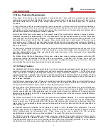
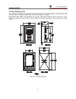
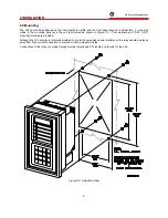
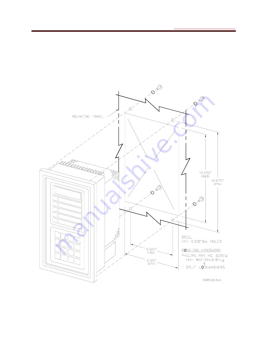
The 169 should be positioned so that the display is visible and the front panel keypad is accessible. A cut-out is
made in the mounting panel and the unit is mounted as shown in Figure 2-3. Four washers and 10-32 X 3/8"
mounting screws are provided.
Although the 169 circuitry is internally shielded, to minimize noise pickup and interference the relay should be placed
away from high current conductors or sources of strong magnetic fields.
Connections to the relay are made through terminal blocks and CTs located on the rear of the unit.
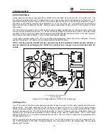
Figure 2-3 Relay Mounting
Summary of Contents for 169
Page 12: ......
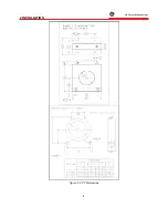
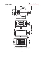
Page 14: ...2 INSTALLATION g GE Power Management 8 Figure 2 2 CT Dimensions ...
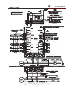
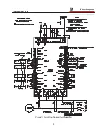
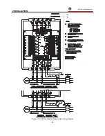
Page 17: ...2 INSTALLATION g GE Power Management 11 Figure 2 4 Relay Wiring Diagram AC control power ...
Page 19: ...2 INSTALLATION g GE Power Management 13 Figure 2 6 Relay Wiring Diagram Two Phase CTs ...
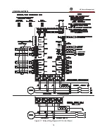
Page 20: ...2 INSTALLATION g GE Power Management 14 Figure 2 7 Relay Wiring Diagram DC Control Power ...
Page 28: ...2 INSTALLATION g GE Power Management 22 Figure 2 10 169 Drawout Relay Physical Dimensions ...
Page 29: ...2 INSTALLATION g GE Power Management 23 Figure 2 11 169 Drawout Relay Mounting ...
Page 31: ...3 SETUP AND USE g GE Power Management 25 Figure 3 1 Front Panel Controls and Indicators ...
Page 73: ...3 SETUP AND USE g GE Power Management 67 Figure 3 2 Standard Overload Curves ...
Page 74: ...3 SETUP AND USE g GE Power Management 68 A B Figure 3 3 Custom Curve Examples ...
Page 88: ...5 THEORY OF OPERATION g GE Power Management 82 Figure 5 1 Hardware Block Diagram ...
Page 90: ...5 THEORY OF OPERATION g GE Power Management 84 Figure 5 2 Firmware Block Diagram ...


