background image


OPM_MLE_LTE_350_1K0_1GB_V011


3


DE ML Series: user manual 1.1 (GB)


GE Digital Energy


ML Series

g


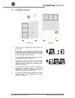
2.2 Installation 

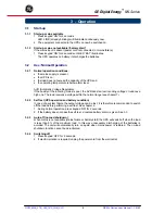
Procedure 


1. 

Switch off your computer, and unplug it from the 

socket-outlet. 


2. 

Disconnect the power cord from the computer (rating 

250Vac/10A) and connect this cord to the male input 

socket (2) at the rear of the UPS (figures on the right 

show simplified ML 350-700 model). 


3. 

Using the output cord provided, connect the computer 

to the appliance outlets (3) of the unit. 


4. 

Connect the mains cord of the UPS to a working, 

grounded AC wall socket outlet. The green LED 

'LINE' will blink now: mains power is available and the 

batteries are charging. 


5. 

For best results, allow the UPS to recharge the 

batteries for a period of approx. 10 hours. It is 

acceptable to use the UPS without first charging the 

battery, but the runtime may be reduced. 


6. 

For advanced communication possibilities, the RS232 

interface port (4) can be connected to a computer 

system. See chapter 4. 


ML 350-700 

ML 1000 

Summary of Contents for 1000 VA

Page 1: ...000 VA Manufactured by GE Digital Energy General Electric Company Telephone 41 0 91 850 51 51 CH 6595 Riazzino Locarno Fax 41 0 91 850 51 44 Switzerland Website www gedigitalenergy com Technology for...

Page 2: ...ATION 2 2 1 Installation Rules 2 2 Installation Procedure 3 OPERATION 4 3 1 Start up 3 1 1 Start up mains available 3 1 2 Start up mains not available battery start 3 2 Use Normal Operation 3 2 1 Norm...

Page 3: ...lly Connect the unit to a wall outlet for a period of approx 48 hours minimum every 3 months The shipping box contains a Digital Energy ML Series UPS a power cord a computer interface cable a CD ROM a...

Page 4: ...he output cord provided connect the computer to the appliance outlets 3 of the unit 4 Connect the mains cord of the UPS to a working grounded AC wall socket outlet The green LED LINE will blink now ma...

Page 5: ...g mains is poor the AVR boosts a low incoming voltage or reduces a high one The load receives a voltage within the normal range see chapter 7 3 2 2 Self test UPS operation and battery condition In cas...

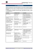
Page 6: ...ible Replace battery 3 3 5 Mains on UPS output on UPS has failed to pass the previous self test Green on mains mode Green blinking 1x sec standby mode Red blinking 1x 30 sec Beeps 1x 30 sec Overload o...

Page 7: ...ted power during battery operation the UPS output will be switched off immediately during mains operation the UPS output will be switched off after 30 seconds 3 3 7 Self test The self test can be star...

Page 8: ...ng the batteries use the same number and voltage V capacity Ah Proper disposal or recycling of the batteries is required Refer to your local codes for disposal requirements Never dispose of batteries...

Page 9: ...e above No communication between computer and UPS Computer interface problem Check interface cable and attached computer Blown input fuse See above UPS operates on battery though mains is present Very...

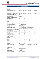
Page 10: ...r factor 0 6 0 7 at 90 load Transfer time ms typically 4 max 10 Buck Boost voltage regulation if the input voltage is within the input voltage window the output voltage varies between 198 265Vac Batte...

Reviews: