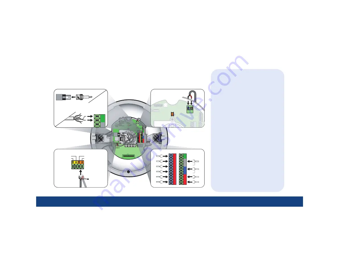
3 | Wiring
TIPs
•
For
data
, you have the choice of
connecting UTP for RS-422 or
connecting STP for RS-485.
- If you are installing RS-485,
float the shield at the dome and
ground it at the keypad.
- If you are daisy-chaining domes,
connect the incoming and outgoing
cables to the MAIN terminals.
•
For
video
, you have the choice of
connecting UTP or coaxial.
- If you are installing coaxial video,
use only crimp-on BNC connectors.
•
For
power
, feed the cable over the top
of the upper bracket,
never through the
center
. Power is not polarity sensitive.
•
For
alarms
, use dry contacts.
•
For
relays
, use a maximum operating
voltage of 30 VAC, 30 VDC at 0.5 A.
•
Because of space constraints, if you are
installing more than five alarms and/or
relays, use a multiple-conductor cable
instead of individual single-pair cables.
•
If heaters are present, route all cables
away from them.
ETHERNET
COAXIAL
VIDEO
INTERCONNECT CARD
DATA
~
2
I/C
3
I/C
4
I/C
5
I/C
6
--
+
O/C
N/O
N/C
O/C
N/O
N/C
I/C
8
I/C
AUX
ON
0
5
1
6
2
7
3
8
4
9
0
5
1
6
2
7
3
8
4
9
B
3
F
7
D
5
1
9
C
4
0
8
E
6
2
A
B
3
F
7
D
5
1
9
C
4
0
8
E
6
2
A
1's
10's
100's
PROTOCOL
AUX RS485--
AUX RS485+
MAIN RS485/422--
MAIN RS485/422+
U--
U+
C
C2
1
1C
2
HEATER/BLOWER
HEATER/BLOWER
(1 of 2)
RE
R
OR
O
FOR FUTURE USE
HEATER
THERMOSTAT
POWER
~
~
1
I/C
2
I/C
3
I/C
4
I/C
5
I/C
6
I/C
--
+
O/C
N/O
N/C
O/C
N/O
N/C
I/C
8
I/C
7
--
+
O/C
N/O
Wiring
For complete cabling requirements and installation instructions, see the installation manual.
All cables are connected to the housing board in the housing. Addressing, protocol, and
termination are set on the active housing board.
Data
Note:
AUX is
for future use.
Note:
Float
shield for
RS-485.
Video
Power
Alarms/relays
Coaxial
UTP
— or —


