background image

GCI E84 Emulator Getting Started Manual

Version 2.4a

GCI E84 Emulator Getting Started Manual

11

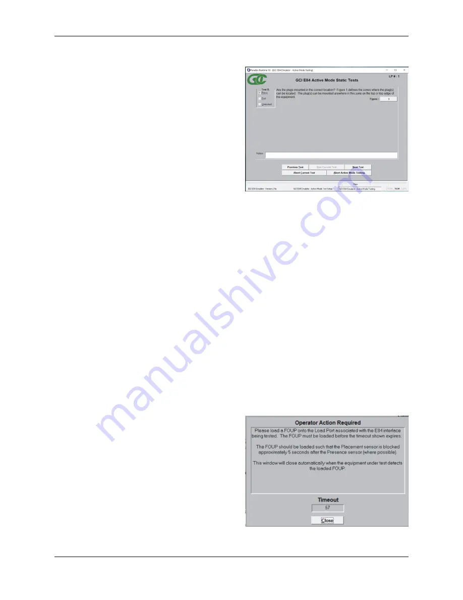
Automated Active Mode Test Screen

Operator Action Required Screen

Automated Test Screens

An 

Automated Test Screen

 is used to display test status

information during automated testing. 

The 

E84 Test Plan

 for Single and Simultaneous

Handoff mode testing includes two types of Automated
Tests, Static and Functionality.  Static mode tests
require the user to mark the test results manually. 
Typical Static tests include verification of proper E84
plug location.  

Static mode tests must be passed / failed by the user. 
The user must mark the test results by clicking with the
mouse, or using the hot-key combination from the
keyboard.  Hot keys for the three available test results
are: Alt-P (Pass), Alt-F (Fail), Alt-U (Untested).  

The second type of Automated Tests defined by the 

E84 Test Plan

 is Functionality tests.  These tests are

automated by the 

E84 Emulator

, and include several individual steps to complete.  During Functionality

testing, a flashing “Please Wait - Testing” message is displayed directly below the test title.  As each step
of the current Functionality test is completed, a test step message is displayed in the large, center window
of the 

Automated Test Screen

.  This window gives a detailed history of the steps completed for the given

test.  If the test fails, the test step that the failure occurred is displayed in this window, along with a failure
message.

Continuous Handoff Mode testing involves running several separate handoff’s sequentially.  An typical
Continuous Handoff Mode test might first Unload the carrier on Load Port CS_0, then load a new carrier to
the same Load Port.  For Continuous Handoff Mode testing, the test step details for each individual
handoff is displayed during the handoff.  At the end of each individual handoff, the message is displayed
indicating that the 

E84 Emulator

 is processing the TD1 delay timer.  This timer (defined by the SEMI

®

 E84

Specification as a delay time between the VALID signals of two successive handoff’s) is used to separate
two handoff’s.

When the TD1 timer has expired, the center window on the 

Automated Test Screen

 is cleared, and the

test steps for the next handoff are displayed.

During Continuous Handoff Mode testing, a C

URRENT 

C

YCLE

 field is displayed above the test step detail

window, indicating the current handoff being tested. 

Operator Action Required Screen

Most Functionality tests include at least one test step
that requires the user to perform some action.  A typical
action would be loading a FOUP onto the Load Port
during a Load Cycle test.   When one of these test steps
is processed, an 

Operator Action Required Screen

 is

displayed, detailing the specific action required by the
user.

Some of these required actions must be completed
within a certain time frame.  Continuing the example
started above, during a Load cycle test, the 

E84

Emulator

 follows the proper handshaking with the

process equipment until the point where the process
equipment expects to see the FOUP loaded into its
Load Port.  The process equipment places a timeout

Summary of Contents for E84

Page 1: ...GCI E84 Emulator Getting Started Version 2 4a...

Page 2: ......

Page 3: ...d Test Setup Screens 7 Select Default Tests Button 8 Select Unload Port Tests Button 8 De Select All Tests Button 8 Test Setup Option Buttons 8 Continuous Handoff Test Setup Screen 9 Defining the Cont...

Page 4: ...ssive Equipment Female DB 25 connector 4 Example Single Handoff Mode Transfer 5 Example Simultaneous Handoff Mode Transfer 5 Example Continuous Handoff Mode Transfer 6 Main Menu 7 Automated Active Mod...

Page 5: ...ndoff sequences are supported including Single Simultaneous and Continuous modes E84 Emulator Application Version 2 4a requires a USB Interface E84 Emulator whose hardware has been updated to version...

Page 6: ...tory within the C Program Files or C Program Files x86 directory structure is not recommended and may cause unexpected application behavior When installation is complete a dialog box is displayed indi...

Page 7: ...module It is labeled PC INTERFACE Powering Up the E84 Emulator Plug the provided standard power cord into the E84 Emulator and into a 100V 240V AC wall outlet Turn the power switch on The power switch...

Page 8: ...lower left of the Main Menu It will display Communications Mode USB when the E84 Emulator Application is properly communicating with the E84 Emulator USB Interface When the user attempts to use any o...

Page 9: ...doff sequence The figure at right shows E84 interface signals recorded during a typical Single Handoff Mode transfer The timing diagram shows the CS_0 signal turning ON to indicate a Single Handoff Mo...

Page 10: ...1 VALID TR_REQ BUSY COMPT CONT HO_AVBL ES Example Continuous Handoff Mode Transfer The 15 passive mode tests provided by the E84 Emulator Application can be also run in Simultaneous Handoff Mode as we...

Page 11: ...e Active entity Attach the female end of a straight through 25 pin male to female cable provided to the DB 25 connector labeled EMULATOR IS ACTIVE EQUIPMENT on the E84 Emulator Attach the male end of...

Page 12: ...s to run This provides a quick method of selecting all tests For Passive Mode testing this is the only function of the Select Default Tests button For Active Mode testing this button has one additiona...

Page 13: ...the end of this manual Defining the Continuous Mode Test Sequence List A DEFINE CONTINUOUS MODE TEST SEQUENCE box allows the user to define the specific order of handoff s to run during Continuous Han...

Page 14: ...one step in the SELECTED CYCLES list The bottom button displayed as a downward pointing arrow moves the selected cycle down one step in the SELECTED CYCLES list Default Cycles Buttons A set of Defaul...

Page 15: ...sage Continuous Handoff Mode testing involves running several separate handoff s sequentially An typical Continuous Handoff Mode test might first Unload the carrier on Load Port CS_0 then load a new c...

Page 16: ...Pass Fail status of the test based on feedback unavailable to the E84 Emulator from the equipment being tested For example when testing passive equipment timeout settings the E84 Emulator will force...

Page 17: ...t signals The Passive Mode Manual Control Screen allows toggling of all Passive E84 output signals The screen also displays the live status of the Active equipment s output signals No automated timing...

Page 18: ...evious versions did not monitor the ES signal during timeout and port sensor tests This falsely passed load ports that dropped ES along with HO_AVBL on timeout errors This change properly implements t...

Page 19: ...on numbers in your email along with the following details The Test Mode Active Passive or Continuous you are running The Test Number and State where the problem is occurring Any Error messages display...

Reviews: