background image

12

LaserPro C180 User Manual

Please take some time to familiarize yourself with this section regarding the mechanical overview of the
LaserPro C180 / C180S. References will be made back to the different parts of the LaserPro C180 / C180S 
in later sections.

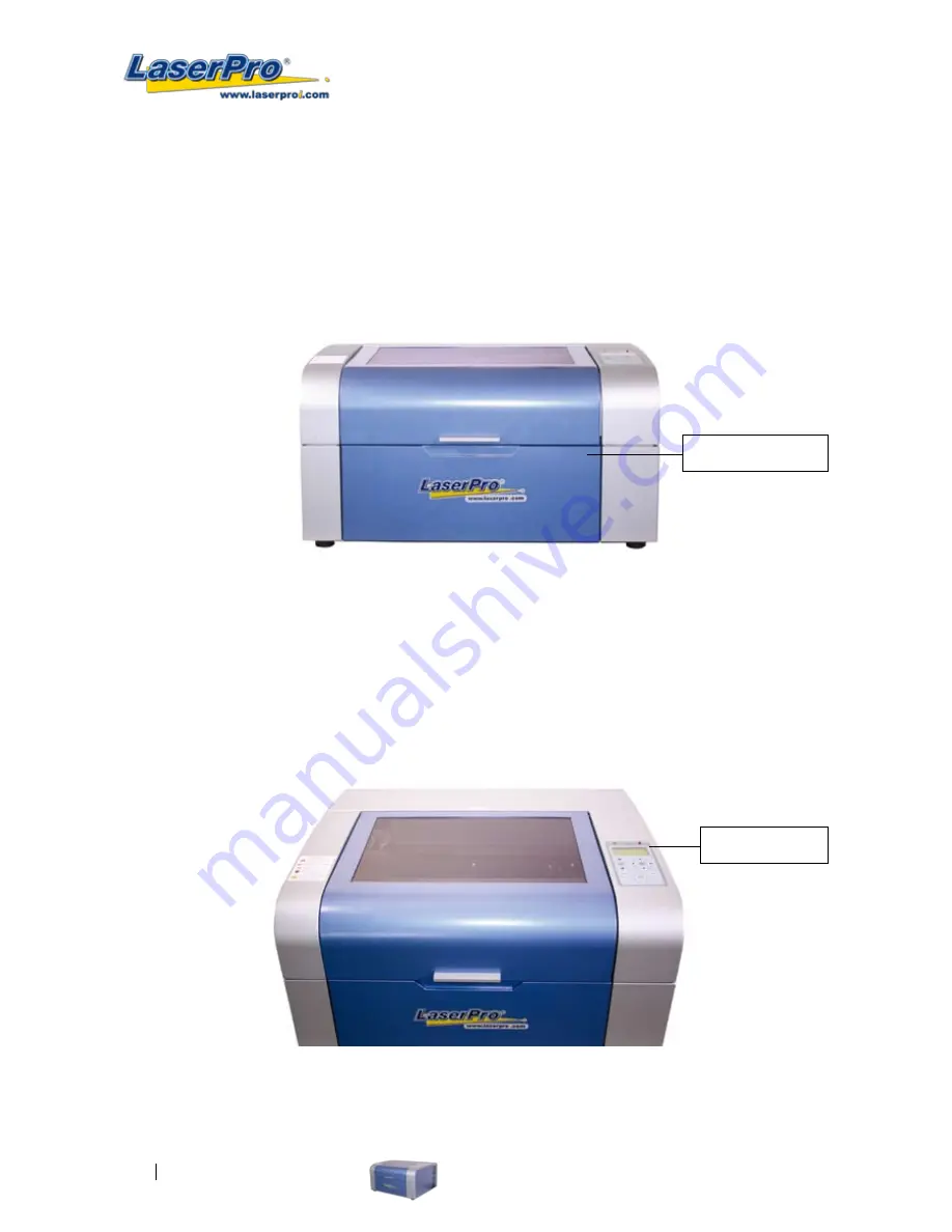
3.1 Front View
                       

3.2 Top View


Lower Front Door 

Control Panel 

Summary of Contents for LaserPro C180

Page 1: ......

Page 2: ......

Page 3: ...m the C180 clearly on the cutting edge of all laser systems GCC understands that a creative technical background is the key to successful growth in the ever changing information economy We have a stro...

Page 4: ...r 18 4 2 Graphics Software Setup 19 4 2 1 Recommended Computer Configuration 19 4 2 2 Installation of the LaserPro USB Driver 20 4 2 3 Installation of the LaserPro Print Driver 26 Chapter 5 Operating...

Page 5: ...mb Table Option 84 7 4 SmartAIR Nozzle Fine Ultra Option 84 7 5 SmartGUARD Fire Alarm Option 85 7 6 SmartMEMORY Module Option 86 7 7 Rotary Attachment Option 88 Chapter 8 Basic Maintenance 93 8 1 Sugg...

Page 6: ......

Page 7: ...1 Chapter 1 Safety Principles of CO2 Laser Safety Ratings The Safety Interlock System Safety Labels Safety Measures Operating Environment LaserPro C180 User Manual 1...

Page 8: ...chine 1 3 The Safety Interlock System The laser system is equipped with a safety interlock system utilizing magnetic sensors on the top and side access doors laser activation and door LED lights on th...

Page 9: ...rself with the specific labels and their locations on the machine Below is a list of all the safety labels and their locations on the machine Product Label This label is located at the right back side...

Page 10: ...f possible laser paths as a reminder Operators should exercise caution when working close to these laser paths to avoid possible injury while machine is turned on CAUTION AVOID PLACING YOUR EYES IN TH...

Page 11: ...enameled brass and anodized aluminum may partially reflect some of the invisible laser radiation Severe eye damage may occur if appropriate safety goggles are not worn NOTE Each LaserPro laser machine...

Page 12: ...near the dew point Avoid small enclosed areas with poor ventilation Avoid areas with high levels of noise and electrical noise Select a location that is large enough to accommodate the LaserPro C180 a...

Page 13: ...LaserPro C180 User Manual 7 2 Chapter 2 Unpacking Contents Unloading and Unpacking Contents and Accessories Checklist...

Page 14: ...s for unpacking and assembly of the machine WARNING To prevent personal injury or damage to the machine please obtain assistance when loading and unloading the shipping crate NOTE Please save the orig...

Page 15: ...LaserPro C180 User Manual 9 3 Open the carton box 4 Carefully lift the machine out of the box with the help of another person...

Page 16: ...ms are missing immediately contact your local GCC distributor ITEM QUANTITY Cleaning Kit Cotton 1 Lens Cleaner Solution 1 Lens Tissue 1 Main Power Cord 1 Printer Port Cable 1 USB Port Cable 1 Focusing...

Page 17: ...LaserPro C180 User Manual 11 3 Chapter 3 Mechanical Overview Front View Top View Right Profile View Left Profile View Rear View Difference between C180 and C180S View...

Page 18: ...amiliarize yourself with this section regarding the mechanical overview of the LaserPro C180 C180S References will be made back to the different parts of the LaserPro C180 C180S in later sections 3 1...

Page 19: ...LaserPro C180 User Manual 13 3 3 Right Profile View 3 4 Left Profile View Power Switch Power Cable Inlet...

Page 20: ...View C180 LED lighting Openings for jigs and air suction Built in SmartBOX Internal side covers Note Working platform can be removed from SmartBOX for extra 2 engraving depth allowing work done on 6...

Page 21: ...LaserPro C180 User Manual 15 C180S No LED lighting No Openings for jigs and air suction No Built in SmartBOX No Internal side Note Without the SmartBOX the maximum engravable depth of the object is 4...

Page 22: ......

Page 23: ...p and Installation Machine Setup Powering Up the Machine Power Cable Connection Connecting the Computer Graphics Software Setup Recommended Computer Configuration Installation of the LaserPro USB Driv...

Page 24: ...neath the control panel 4 1 3 Connecting the Computer The LaserPro C180 can communicate with a computer through a USB Port or Parallel Printer Port connection interface The USB Port connection offers...

Page 25: ...will suggest that you can select AutoCAD to work with the LaserPro C180 to have better output performance 4 2 1 Recommended Computer Configuration The LaserPro C180 operates under Windows operating sy...

Page 26: ...LaserPro print driver installation Install the LaserPro USB driver BEFORE installing the LaserPro C180 print driver This set of USB drivers are not the same as the native USB drivers for Microsoft Wi...

Page 27: ...m Installation Process Step1 Download the latest USB driver Step 2 Please do the following steps to install the USB driver 1 Run the remove exe right click and click Run as Administrator to make sure...

Page 28: ...22 LaserPro C180 User Manual 2 Run the USBSETUP EXE file right click and click Run as Administrator...

Page 29: ...ager and locate the Universal Serial Bus Controllers Attention Remove previous installations if any Right click on previous installations and select remove driver then unplug and plug USB cable from l...

Page 30: ...r exe under Win Vista Even if the GCC USB has been installed correctly it will still not work correctly when you are not logged in as an administrator to run the Upgrader exe file Example 1 If we run...

Page 31: ...erPro C180 User Manual 25 Example 2 Under the same situation as sample 1 right click on the Upgrader exe and click Run as Administrator you can see the GCC USB Port in the pull down list of the Com Se...

Page 32: ...g Driver and click Next to continue 9 This screen will prompt you to provide a printer name Simply type in C180 and select Yes or No if you want to use this printer as the default printer and click Ne...

Page 33: ...Graphic Control Panel Function Pages The LaserPro C180 Print Driver Page Setup and Orientation Color Management Using the LaserPro C180 Print Driver LaserPro C180 Print Driver Options Page LaserPro C1...

Page 34: ...ing of your immediate work area you may need to adjust the LCD display screen s contrast You may increase or decrease the display screen s contrast via the contrast adjustment wheel found on the insid...

Page 35: ...ough doors of the machine Operator must wait for 8 seconds before the laser tube can begin to work A 40 seconds laser warm up period is required after the machine is turned on A warning will be displa...

Page 36: ...tment Page Quick List Page Machine Settings Page Recall Position Page Select Focus Lens Page Machine Information Page Save Position Page SmartMemory Page Tune Auto Focus Page Carriage Free Page SmartG...

Page 37: ...the various functions of the control panel This will be the page that is displayed when you are processing your jobs This page contains specific job information such as the current job s name Speed Po...

Page 38: ...Directional Manually adjust the Y axis position of the laser carriage Directional Manually adjust the X axis position of the laser Enter Selects the indicated option Menu Go to Menu Page A F Initiate...

Page 39: ...allows you to access and modify a variety of your machine settings including Command Mode and Laser Tube Model Machine Information Page this page allows you to view information regarding the system s...

Page 40: ...al No Action Enter Selects the indicated option Menu Go to Menu Page A F Initiate the auto focus function A F Directional Manually adjust the height of the work table Z axis Start Pause Go to Main Wor...

Page 41: ...No Action Enter Selects the indicated option Menu Go to Menu Page A F Initiate the auto focus function A F Directional Manually adjust the height of the work table Z axis Start Pause Go to Main Work...

Page 42: ...ions Directional No Action Enter Selects the indicated option Menu Go to Menu Page A F Initiate the auto focus function A F Directional Manually adjust the height of the work table Z axis Start Pause...

Page 43: ...Page Relevant Buttons Function Directional Scroll through options Directional No Action Enter Selects the indicated option Menu Go to Menu Page A F Initiate the auto focus function A F Directional Ma...

Page 44: ...tion Directional Scroll through options Directional No Action Enter Selects the indicated option Menu Go to Menu Page A F Initiate the auto focus function A F Directional Manually adjust the height of...

Page 45: ...Select Focus Lens Page Relevant Buttons Function Directional No Action Directional Scrolls through options Enter Saves the indicated option Menu Go to Menu Page A F Initiate the auto focus function A...

Page 46: ...ctional No action Enter Saves the current focal distance Menu Go to Menu Page A F Initiate the auto focus function A F Directional Manually adjust the height of the work table Z axis Start Pause Go to...

Page 47: ...he control panel Carriage Free YES NO Carriage Free Page Relevant Buttons Function Directional No action Directional Scroll between Yes No Enter Saves the current setting Menu Go to Menu Page A F Init...

Page 48: ...are five sensitivity settings 1 3 5 7 9 seconds that can be selected Sensitivity is defined by the delay time from when a fire is detected until the fire alarm alerts user of fire and automatically sh...

Page 49: ...auto focus function A F Directional Manually adjust the height of the work table Z axis Start Pause Go to Main Work page Stop Go to Main Work page Back Go to previous screen Light Turn Light On Off O...

Page 50: ...file Alarm setting will enable or disable an audible notification when your jobs are completed Language ENGLISH others dependent on Firmware Unit METRIC ENGLISH EOF Alarm YES NO Others Page Relevant B...

Page 51: ...and continue System Reset a confirmation will pop up press Enter to confirm and continue Reset Page Relevant Buttons Function Directional Scroll between selections Directional Scroll between selection...

Page 52: ...Scroll between selections Directional No Action Enter Select indicated option Menu Go to Menu Page A F Initiate the auto focus function A F Directional Manually adjust the height of the work table Z a...

Page 53: ...indicated option Menu Go to Menu Page A F Initiate the auto focus function A F Directional Manually adjust the height of the work table Z axis Start Pause Go to Main Work page Stop Go to Main Work pa...

Page 54: ...croll between selections Enter Select indicated option Menu Go to Menu Page A F Initiate the auto focus function A F Directional Manually adjust the height of the work table Z axis Start Pause Go to M...

Page 55: ...rectional Show more info Directional No action Enter No action Menu Go to Menu Page A F Initiate the auto focus function A F Directional Manually adjust the height of the work table Z axis Start Pause...

Page 56: ...ER you may set it up through the graphics software as well The following is taking Corel Draw as example of how to set up LaserPro C180 as the Printer 1 From the primary menu click FILE PRINT SETUP 2...

Page 57: ...the left click DOCUMENT PAGE SIZE 5 Ensure that NORMAL PAPER and LANDSCAPE are selected 6 Ensure the Paper Width and Height dimensions match the LaserPro C180 s work table dimensions of 458 mm 18 inc...

Page 58: ...s software used for this example For other graphics software you will need to access the corresponding Color Management page 1 From the primary menu click TOOLS COLOR MANAGEMENT and CorelDRAW s Color...

Page 59: ...age Raster Page appears only in Black White Mode Stamp Page appears only in Stamp Mode Tip The following sections describe the specific functions for each of the settings found in the LaserPro C180 Pr...

Page 60: ...menu Please refer to the next section of the manual for details regarding the PEN functions The LaserPro C180 print driver will interpret colored and shaded areas as different shades of gray by produ...

Page 61: ...tion page and PPI power and speed settings Pen page Stamp Mode Select this mode to when you would like to engrave stamps The stamp mode is one of the more dynamic functions of the LaserPro C180 Due to...

Page 62: ...image the white areas become black and vice versa The Invert option is not available in disabled with Manual Color File mode selected Print Immediately Option Page DEFAULT SETTING Unselected Checking...

Page 63: ...s as the default startup settings DELETE This function will delete the file you select from the History File section Please note the delete function only removes the file from the history file section...

Page 64: ...58 LaserPro C180 User Manual...

Page 65: ...r to utilize up to 16 different pens laser parameter settings make sure your graphics software can recognize and utilizes the 16 pen colors designated by the LaserPro C180 print driver If you would li...

Page 66: ...om 1 100 The percentage setting represents the power for each laser pulse fired Tip Cutting engraving depth and quality are determined by a combination of power and speed Slower speeds at higher power...

Page 67: ...tor will force the driver to process ignore the color fills thin lines Vector Checked Vector Unchecked Raster Checked Processes both Vector and Raster functions for that particular color Processes onl...

Page 68: ...he last position of the previous job Relative This mode sets the current laser head position to correspond to the origin top left position of the graphic software Therefore the laser head will process...

Page 69: ...the default Vector Function setting All Raster Output This selection will instruct the print driver to process your entire image as a raster engraving Any vector lines within the image will be treated...

Page 70: ...the distance to a value less than 20 By doing so the laser will completely process one square and leap frog to the second square rather than processing both squares simultaneously The result you short...

Page 71: ...ion you will need to adjust the image tuning setting To adjust this setting we recommend you engrave a small black square design as a sample and apply a magnifying glass to the engraved results When y...

Page 72: ...rotary attachment properly set up 1 Check the Rotary Fixture function and notice the change in the Paper Size fields Under Paper Size the X value represents the length of your work piece Enter the le...

Page 73: ...int Driver Available language options include English Spanish French Japanese German Simplified Chinese and Traditional Chinese 5 2 3 6 C180 Print Driver Raster Page NOTE The Raster Page is only avail...

Page 74: ...onal output options yielding different output effects style and quality Dithering Interprets and outputs the raster engraving via the dithering method This mode will allow you to select the Pattern Ty...

Page 75: ...Floyd Each diffusion type presents the shade of image as different spread halftones instead of dots to compose a raster image The following diagram is an example of the raster effects when using the d...

Page 76: ...houlder Pitch Border Invert and Mirror Pitch Stamp Page Your stamp will be a reversed image composed of engraved depressions and ridges Think of these ridges as the contact sections of the stamp If th...

Page 77: ...base This function allows you to adjust the slope for the shoulder sections of your stamp By sliding the sliders or directly input of power levels you will be able to change the slope of the shoulder...

Page 78: ......

Page 79: ...LaserPro C180 User Manual 73 6 Chapter 6 Engraving and Cutting Techniques Raster Engraving Vector Cutting Vector and Raster 3D Tips Modify Image Setting of a Picture for Better Engraving Quality...

Page 80: ...f a raster engraved piece would be a photo engraving on tile as shown in the picture below 6 2 Vector Cutting A laser engraver can process text design and images composed of lines through continuous f...

Page 81: ...selected characters outline thickness to the thinnest width by right clicking on the selected text select Properties Click on the Outline tab and change the Width to its thinnest dimension Click on O...

Page 82: ...2nd pass will smooth out the surface For engraving wood as it burns easily and leaves blackened surface after the 1st pass it is necessary to run the 2nd pass to remove the burned surface To do that...

Page 83: ...LaserPro C180 User Manual 77 5 Convert the image to Bitmap by selecting the image and click on Bitmaps Convert to Bitmap...

Page 84: ...78 LaserPro C180 User Manual 6 Change the Bitmap settings by setting Color to Grayscale 8 bit and Resolution to 300 dpi and click OK 7 Finally Invert the image by selecting Effects Transform Invert...

Page 85: ...E This instruction is a simple example for general use There are many tips and tricks to achieve a good engraving quality It takes a lot of practice and experience to achieve a good engraving quality...

Page 86: ......

Page 87: ...nual 81 7 Chapter 7 Optional Items Air Extraction System Option Air Compressor Option Items Honeycomb Table Option SmartAIR Nozzle Fine Ultra SmartGUARD Fire Alarm Option SmartMEMORY Module Option Rot...

Page 88: ...features Each LaserPro Air Extraction System is powered by a maintenance free continuous running turbine In order to ensure personnel safety and legal compliance the LaserPro Air Extraction System is...

Page 89: ...the air compressor provides the optimal air flow to the SmartAIR nozzles to minimize flaming suppress working temperatures and blow away dust and particle byproducts generated from the laser process 1...

Page 90: ...ON 1 Switch on the air compressor unit and make sure that the airflow regulator on the air assist valve is opened turn clockwise to increase the airflow counter clockwise to decrease the airflow The a...

Page 91: ...et to notify the operator through audio warnings and automatically shutdown the machine as a safety precaution INSTALLATION If you have purchased your system with SmartGUARD then no installation is re...

Page 92: ...and load your working files to and from the C180 In addition the SmartMEMORY module is portable and can be used to transfer task settings from one machine to another INSTALLATION CAUTION It is highly...

Page 93: ...he SmartMEMORY module is 4MB please do not save files that exceed this limit SAVE files to the SmartMEMORY module 1 Navigate to the Write Flash Memory function From the C180 Control Panel press the F4...

Page 94: ...ameter Large conical fixture 90 mm 3 7 inches Maximum Diameter Large conical fixture 125 mm 5 inches INSTALLATION 1 Open the front panel of the LaserPro C180 lower the working platform to the bottom 2...

Page 95: ...ll automatically move to its lowest position NOTE For machines without the built in SmartBox the rotary attachment is positioned on the working table and the max diameter of the object is 0 5 1 9 For...

Page 96: ...diameter of your work piece in this field Again remember the proper diameter value would be the diameter location on your work piece you will be engraving c Under Rotary Parameter the Offset value rep...

Page 97: ...fixture 50 mm and 250 mm Big conical fixture 127 mm and 250 mm Maximum weight should not exceed 5 kg Exchanging the conical fixtures on the rotary attachment A Remove the 2 screws shown in the picture...

Page 98: ...ent as shown below D Use the flat surface as shown in picture below as a reference point and tighten the first screw against it After doing so tighten the second screw and the rotary attachment is rea...

Page 99: ...ggested Cleaning and Maintenance Supplies Maintaining the Work table and Motion System Cleaning the Work table and Motion System Lubrication of the Y Rails Cleaning the Optics System Removing the Mirr...

Page 100: ...work environment the frequency of use the quality of the exhaust system etc WARNING Electrical shock may occur if you do not turn off and unplug the C180 before cleaning Damage may occur to the syste...

Page 101: ...and operating the C180 CAUTION Never pour or spray alcohol or acetone directly to the working table Oil alcohol and acetone can cause fires or smoke build up if improperly used Tip Please clean the A...

Page 102: ...ove each of the four mirrors found on the LaserPro C180 for cleaning Mirror 1 This mirror is located inside the bottom left access panel of the LaserPro C180 1 Use a 2 Phillips Screwdriver to remove t...

Page 103: ...Mirror 4 Mirror 3 Mirror 3 1 Unscrew the thumbscrew holding mirror 3 in place 2 Clean the lens in the proper manner 3 Re install mirror 3 after cleaning 4 Tighten the thumbscrew Mirror 4 1 Unscrew the...

Page 104: ...surface 2 Drape a new sheet of lens tissue over the mirror 3 Apply a few drops of lens cleaner on the tissue covered mirror apply enough so that the tissue absorbs just enough to cover the mirror sur...

Page 105: ...ens with a cotton swab and lens cleaner solution Be sure to clean both sides of the focal lens DO NOT apply any pressure or other cleaning solutions to the lens surface 4 After cleaning use a cotton s...

Page 106: ......

Page 107: ...LaserPro C180 User Manual 101 Chapter 9 Basic Troubleshooting 9...

Page 108: ...r power connector is loose 4 For safety purpose the laser beam will not be generated when the top or front door is opened unless you short the connector of the magnetic switches NOTE Unplug the machin...

Page 109: ...LaserPro C180 User Manual 103 Chapter 10 Appendix 10 Glossary LaserPro C180 Series Specification Sheet...

Page 110: ...imultaneously Another common name for the parallel port is the LPT port PPI Pulses Per Inch PPI determines the gross amount of laser pulses there will be per linear inch PPI is exclusively for the vec...

Page 111: ...Automatic Resolution DPI Available 125 250 300 380 500 600 760 1000 Computer Interface Standard printer port and USB port Compatible Operating Systems MS Windows MAC OS Memory Buffer 32 MB standard U...

Reviews: