background image


Jaguar V User Manual 


Illustrator Plug-In                                A-4 
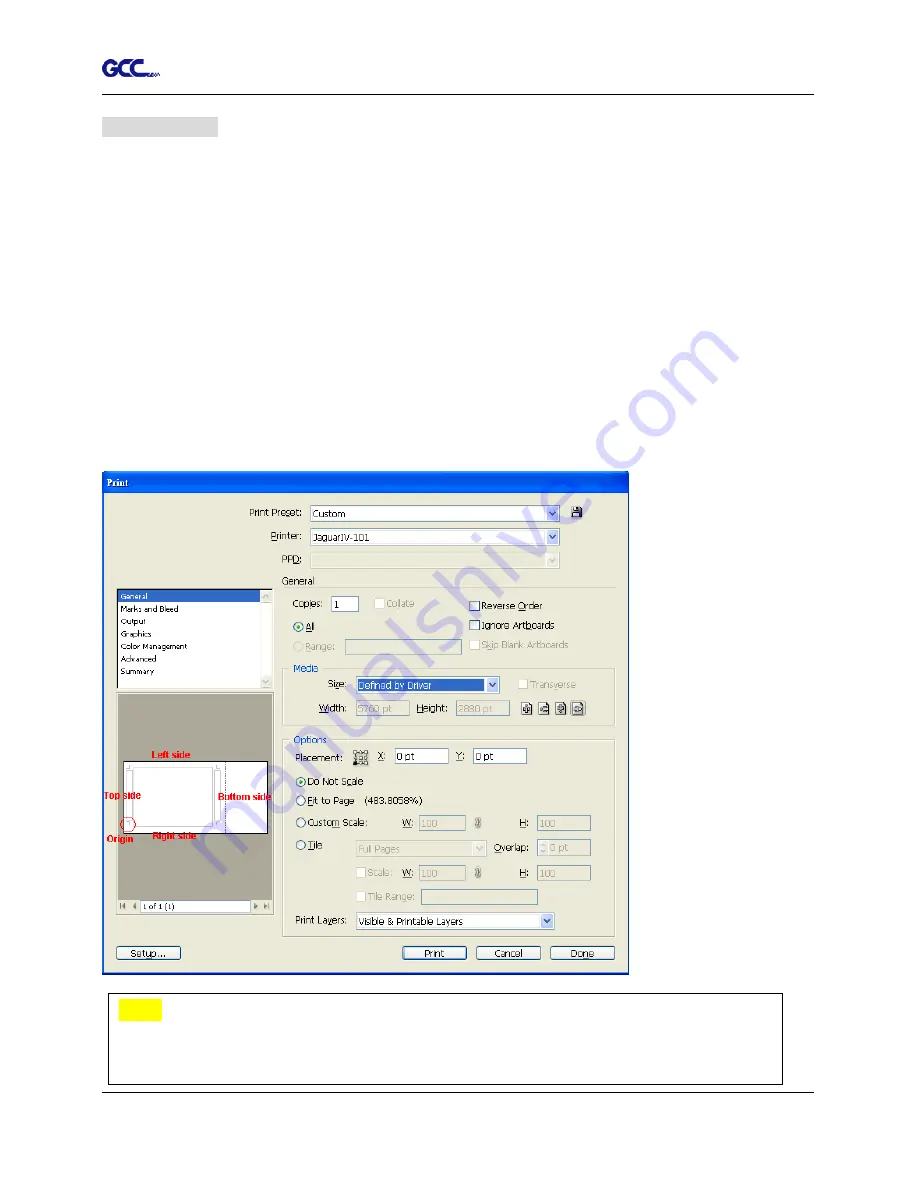
Workable area 

It allows users to edit and cut graphics in the area outside the registration marks when adding 

registration marks by page. 


For A4 size media sheet, the workable area is 2.5mm


extended from the registration mark on 

left and right sides and 4.5mm extended from the registration mark on top side. On the bottom 

side, it is suggested to leave at least 25mm margin from the edge of media sheet to prevent 

sheets dropping or any error occurred while media sizing. 


For A3 size media sheet, the workable area is 10mm


extended from the registration mark on the 

left side, 9mm


extended from the registration mark on the right side and 11mm extended from 

the registration mark on top side. On the bottom side, it is suggested to leave at least 25mm 

margin from the edge of media sheet to prevent sheets dropping or any error occurred while 

media sizing. 


Note:

 Select “

Edge

” mode when media sizing to allow the media sheet to be unrolled. If 

you select “

Single

” mode, the media sheet will not be able to be moved back and hence 

fail to be detected by front paper sensor. 


Summary of Contents for Jaguar J5-101

Page 1: ...V 4 2016 Dec Jaguar V Series User Manual http www GCCworld com...

Page 2: ...y the information contained in this user manual at any time without prior notice un authorized modification copying distribution or display is prohibited All comments queries or suggestions concerning...

Page 3: ...any of the moving parts of this machine such as the carriage Also be careful to make sure that clothing and hair do not get caught Always connect the power cable to a grounded outlet Always use the ac...

Page 4: ...s shown below O CORRECT X INCORRECT Press down DISABLE Press down Stop bar ENABLE Pull up bottom to release grip Note In case the grips clipped together due to your wrong operation please use a pair o...

Page 5: ...tic Blade Length Detection 2 15 2 8 Cable Connections 2 17 2 8 1 USB Interface 2 17 2 8 1 1 Connecting your GCC cutter 2 17 2 8 1 2 Installing the driver 2 18 2 8 1 3 Driver Un installation 2 21 2 8 2...

Page 6: ...Automatic Distinction of the Plot Direction 5 5 5 3 AAS Offset Test 5 6 5 4 Registration Mark Offset Range 5 5 Contour Cutting 5 8 5 8 5 6 Tips for AAS 5 10 6 Basic Maintenance 6 1 Cleaning the cuttin...

Page 7: ...97 1270mm 50 J5 132 LX for media width 50mm 1 97 1594mm 62 7 J5 183LX for media width 300mm 11 8 1900mm 74 8 1 2 Package Items The package of the Jaguar V model contents the items listed below please...

Page 8: ...r V 1 4 Accessories 1 piece of User s Compact Disk 1 piece of AC power Cord 1 piece of data cable USB cable 3m 1 set of Blade Holder Assembly Installed in tool carriage of the cutting plotter 1 piece...

Page 9: ...and 1 LCM showing messages and menus Cutting Pad provides the protection of blade when the blade is cutting Tool Carriage performs the cutting with the installed blade and pen with AAS module Alignme...

Page 10: ...oll Holder holds and supplies the roll media for cutting Roll Holder Guide Bushes serve to keep the roll media in place when media is pulled from the roll T Stand supports the cutting plotter Stand Be...

Page 11: ...rt the AC power cord Power Switch On when switches to I Off to O Figure 1 4 Serial Interface Connector RS232C used to connect the cutting plotter to a computer through a serial interface cable Figure...

Page 12: ...sily from any direction Keep enough space for the machine accessories and supplies Keep the working area stable avoiding sever vibration Keep the temperature between 15 and 30 60 86o F in the workshop...

Page 13: ...t of roll holder 2 pieces 2 pieces of base beams 2 pieces of side beams 1 piece of stand beam 2 pieces of roll holder support 20 pieces of M6 screws 1 piece of M5 L shape hexagon screw driver 1 piece...

Page 14: ...the T stand and follow number to assemble See Figure 2 2 4 2 2 5 There is hexagon socket head screws fasten on the T stand on both side taken as locating pins Step 4 Position the stand beam perpendic...

Page 15: ...er the plotter on the bottom of the plotter there is one hole on each side in the position corresponding to the locating pins so the locating pins can be located into the holes Then insert the screws...

Page 16: ...stand and then tighten them up as shown in Figure 2 2 7 You could decide roll holder support s position by inserting into different holes Step 7 Place the roll holder 1 onto the roll holder support Fi...

Page 17: ...cking roll holder 2 Figure 2 2 9 Step 9 Insert the end of the roll holder without the damper into the left roll holder support and then insert the end of the roll holder with the damper into the right...

Page 18: ...damper until it is securely attached to the right roll holder support Figure 2 2 11 Step 11 Lastly the complete picture will be shown like below Figure 2 2 12 Step 12 Please refer to user manual secti...

Page 19: ...r the stands with Flexible Media Support System only Step 1 Insert the cable tie into the upper hole of cable saddle from bottom to top This side up Step 2 Place the USB cable into the cable tie and t...

Page 20: ...Jaguar V User Manual Installation 2 9 Untied way pull out the cable tie pull up the pin release the cable tie Pull out the cable tie Pull up the pin Release the cable tie...

Page 21: ...xagon screw driver 1 piece of M5 L shape hexagon screw driver 1 piece of M6 L shape hexagon screw driver for adjusting the screws of Roll Holders 1 piece of Installation Guide for Roll Holder Step 2 P...

Page 22: ...assembly and tighten them with M6 L shape screwdriver Like Figure 2 3 3 Step 5 Place the two roll holders into the holes of Roll Holder Support Figure 2 3 4 To install the roll holder with damper plea...

Page 23: ...2 2 5 Instruction of Damper Roller Turn the wheel as instructed below to adjust damping The bigger the number is the stronger the damping The volume symbol sticker indicates the damping level Figure 2...

Page 24: ...bottom of the blade holder Figure 2 5 3 Step 3 Adjust the blade tip to suitable length by screwing Blade tip adjustment screw clockwise or count clockwise Figure 2 5 4 Figure 2 5 4 Figure 2 5 3 Tips T...

Page 25: ...ect pin to eject blade when the blade needs to be replaced Caution The blade will lose its sharpness after a period of usage the cutting quality might be affected By increasing the cutting force it mi...

Page 26: ...rt adjusting 2 Align one of the scales on the blade holder to the mark on the carriage 3 Select Blade Length Adjust under CUT TEST on the LCM enter the blade length wished in Set Length test the blade...

Page 27: ...2 6 4 Figure 2 6 3 5 The screen will show Adjustment completes when the value on the screen is 0 the blade length is perfect and no more adjustment needs to be made Press Enter now to complete the pr...

Page 28: ...Specifications Revision 2 0 Full Speed 2 8 1 1 Connecting your GCC cutter 1 Turn on the machine 2 Connect the USB connector to the machine and then USB driver will installed automatically It will tak...

Page 29: ...o install from the driver list and click on Windows Driver Win 7 and Above Automatic Detection or Windows Driver Win 7 and Above Manual Selection to start installing the Driver and AAS plug in Step 3...

Page 30: ...ll running application programs before you start installing the driver and then click OK Step 7 The installation will take a few minutes to complete and you will see a message below and click on OK up...

Page 31: ...cond time the user will be prompted as to whether a second copy of the driver installation is required 2 If the user selects yes a second copy of the driver will be installed 3 For users who have upgr...

Page 32: ...to remove previous version driver installed on your PC system completely before you can install the latest version successfully Please refer to below steps Step 1 Go to Control Panel Hardware and Soun...

Page 33: ...2 22 Step 2 After removing the unit click on any printer on the page and select Print server properties For Win 7 and above Or right click on blank space and then select Print server properties For Wi...

Page 34: ...Installation 2 23 Step 4 Select the model and click on Remove Step 5 Select Remove driver and driver package and click OK Step 6 Click Yes and then click Delete and OK and the driver installed on PC i...

Page 35: ...COM2 of your host computer 2 Set up the communication parameters Baud Rate and Data Bits Parity to match the setting of software package refer to chapter 3 Misc key description 2 8 3 Ethernet Connect...

Page 36: ...s will be shown on the screen automatically Please make notes of it II Ethernet Connectivity Setup There are two ways to output your plot through Ethernet If you output your plot through GreatCut plea...

Page 37: ...Installation 2 26 Instruction of Ethernet settings for GreatCut Step 1 Open GreatCut and create a new file and cutting line Step 2 Go to Output Devices under Settings Step 3 Select a model at Driver i...

Page 38: ...mplete the driver installation process and your GCC Cutting Plotter is now allowed to network Note If you want to add new local device please go to Output Devices under Settings and press the button o...

Page 39: ...II Output through Ethernet Driver Step 1 Connect Ethernet cable to PC and install Cutter Ethernet driver Then click OK to continue Step 2 Enter the IP Address shown on the control panel and select the...

Page 40: ...cutting plotters directly Option 2 Most cutting software packages are able to emulate HP GL or HP GL 2 commands As long as the file is HP GL or HP GL 2 format the cutting plotter can output the data...

Page 41: ...Jaguar V User Manual Installation 2 30 Step 2 Click Advanced tab then choose Print directly to the printer option...

Page 42: ...b from A PC to the machine to check if A PC is connected to the machine Step 4 Activate A PC s Printer Driver from B PC s Network Step 5 Right click on the printer icon and select Connect to A PC s pr...

Page 43: ...lation 2 9 1 GreatCut Installation Step 1 Click GreatCut Registration in installation DVD to go http gccvoucher eurosystems lu and then enter your voucher code provided when purchasing GreatCut and cl...

Page 44: ...de Step 4 The registration is completed you should receive two emails one is registration confirmation with activation link and another is your license data with ecf file Step 5 Check your email to se...

Page 45: ...Manual Installation 2 34 Step 6 Or click Install GreatCut in installation DVD Step 7 Select a destination folder Step 8 Select Typical and click Next Note You may select custom setup to install addit...

Page 46: ...V User Manual Installation 2 35 Step 9 Select the folder and click Next Default program folder in the start menu is GCC GreatCut 3 Step 10 GreatCut is installing Step 11 Click Finish to complete insta...

Page 47: ...hed to the license data email to install your license data to GreatCut so that you don t need to fill in your information again Step 13 If the license do not install successfully you will need to fill...

Page 48: ...llation Optional Item 2 9 2 1 Auto Installation Step 1 Put your installation DVD into your CD ROM to start the installation The software is compatible with Windows 7 and above and Macintosh OSX 10 6 a...

Page 49: ...der suggested or select a folder you want to install the Sure Cuts A Lot and press Next Step 6 Tick Create a desktop icon if you want to create a shortcut on your desktop and tick Associated scut4 ext...

Page 50: ...tep 7 Don t tick Install USB Driver and tick Launch Sure Cuts A Lot and then press Finish to compete installation Step 8 Run Sure Cuts A Lot Step 9 Press Activate to activate Sure Cuts A Lot Please ma...

Page 51: ...oftware key shown on the DVD front cover to the Serial column and press OK to complete the activation Step 11 Launch Sure Cuts A Lot select My Cutter under Cutter and select Manage Cutters Step 12 Sel...

Page 52: ...should see the Site Code and Activation Code fields appear The Site Code field will be pre filled in and cannot be changed Step 2 Visit http www craftedge com activation surecutsalot via an internet...

Page 53: ...program and hit ok 2 9 2 3 Re install Sure Cuts A Lot Software If you change a new computer you may need to deactivate your Sure Cuts A Lot software and re install it on your new device Go to Deactiv...

Page 54: ...Jaguar V User Manual Installation 2 43...

Page 55: ...tions and error messages Power LED To indicate the power status light up power on light off power off 4 Arrow Keys To move position select function or change setting ENTER To set item or register the...

Page 56: ...F O L W T1M Sending data PAUSE FORCE Force 80 gf OK ENTER use to select ENTER to enable the setting SPEED Speed 72 cm s Select OK ENTER Up Speed 72 cm s Select OK ENTER Quality normal Select OK ENTER...

Page 57: ...increment of 3 cm s Quality Normal Select OK ENTER Up Accel Medium Select OK ENTER High Medium Low Speed 72 cm s Select OK ENTER Square Cut Select OK ENTER CUT TEST Repeat AAS Job Select OK ENTER Pat...

Page 58: ...ENTER Enabled Disabled First Back To Origin Select OK ENTER DHCP Select OK ENTER Enabled Disabled IP Address Select OK ENTER IP Address set Submask set Gateway set MAC Address 00 CF 52 72 03 01 Enabl...

Page 59: ...o resume the process by press Pause Resume key again ONLINE OFFLINE 1 To switch between online mode and offline mode 2 To stop the cutting job or abort the change of setting Once press this key the cu...

Page 60: ...rn to the main menu This option will appear after finishing reading all registration marks Pattern Setting To provide two patterns for cut test Note It is recommended to select Cross if you are workin...

Page 61: ...e rolled media is less than 2 meters or the weight is light it is recommended to set this mode disabled Enable Rear Paper Sensor To detect if the rear paper sensor is covered to determine the followin...

Page 62: ...y the version number of Firmware and FPGA code Select Language To select displayed languages on LCM panel in English Spanish Italian Deutsch Portuguese Polish Turkish or French English Select Units Pr...

Page 63: ...h rollers are raised Figure 4 1 Step 2 Load your media on the platen and slide it under the pinch rollers from either the front side or the backside The alignment rulers on the platen extension will h...

Page 64: ...ep 4 Push the lever backward to lower down the pinch rollers Step 5 Turn on the power the tool carriage will measure the size of the media automatically And the plotting cutter begins to work Note 1 A...

Page 65: ...all pinch rollers Figure 4 5 before the lever is pushed backwards to ensure accurate media width detection 4 1 2 Loading the Roll Media Step 1 Put the roll holder guide bushes on two roll holders Fig...

Page 66: ...is firmly gripped see Figure 4 7 Then put the roll media on the roll holders Adjust the position of the roll media ensure that media flanges are able to run in the grooves of roll holder guide bushes...

Page 67: ...drums Step 6 Push the lever backward to lower down the pinch rollers Step 7 Fix roll holder guide bushes on the roll holder to secure the roll media Step 8 Turn on the power switch and select Roll Edg...

Page 68: ...media length is less than 4 meters leave the margin of 0 5mm 25mm in the left and right edges of the media Figure 4 12 If the media length is greater than 4 meters leave at least 25mm margin on the l...

Page 69: ...t the cutting test position When the cutting test is completed a pattern appears Peel off the pattern to see if it can be easily separated from the media base If yes the setup tool force is appropriat...

Page 70: ...When you are making a long plot with a roll of heavy and wide vinyl paper you need to use the AUTO UNROLL MEDIA function The following parameter settings are to help users get the best cutting qualit...

Page 71: ...ification About the Tool in Appendix After you notice all the above you ll enjoy your gigantic signs production 4 6 When Completing the Cutting Job After completing the cutting job raise the sheet loa...

Page 72: ...aster speeds lower quality The Cutting Quality setting function allows you to adjust and balance vector mode s quality and speed settings based on your specific job Draft Mode offers the highest outpu...

Page 73: ...ng in section 1 it will continue to cut in section 2 The picture is shown as below File Function The file function section allows users to set the parameters of Speed Force Offset and Quality for late...

Page 74: ...our operating system Custom Media This section lists the files for the parameter settings that you have recently created and worked You can save more than 50 files to simplify your cutting job Default...

Page 75: ...tion go to Option tick Die Cut and enter the amount you wish for the Length and Force of both Die Cut and Kiss Cut then click OK see figure 4 20 Figure 4 20 Note The length setting for the cutting lin...

Page 76: ...op following normal operating procedures see figure 4 21 4 7 2 Jaguar V Print Driver setting Paper Page Note 1 The extension of the blade has to be set to cut through both the top layer and the backin...

Page 77: ...tal work area The X value represents the length and the Y value represents the width The paper size should be set as the same as your image so you can get a better cutting quality Unit Paper Page DEFA...

Page 78: ...4 RX Jaguar RX Jaguar Puma EX P Bengal EXII AR 24 RX Jaguar Puma EX P Bengal EXII AR 24 Material Vehicle stickers Reflective film Cardboard Blade red green green Blade tip length mm 0 27 0 5 0 3 Force...

Page 79: ...ug In 08_A 4 Illustrator Plug In 08_A 5 GreatCut Plug In 5 1 Introduction The Jaguar V LX cutting plotters feature a standard Automatic Aligning System AAS II to guarantee precise contour cutting qual...

Page 80: ...m The registration marks have to be Created by cutting software like SignPal or GCC CorelDRAW plug in In black color printing quality of registration marks is essential incorrect misaligned colors blu...

Page 81: ...CorelDraw Plug In Instruction Appendix A 4 Illustrator Plug In Instruction Appendix A 5 GreatCut Plug In Instruction and Appendix A 6 SignPal 10 5 Instruction 1 4 Point Positioning This is the basic...

Page 82: ...section pattern based on the Segmental Positioning parameters Cutting sequence Section1 Section 2 Section 3 Section 4 3 Multiple Copies The function is used to duplicate images to let you cut quantit...

Page 83: ...when the material is reversely fed JAGUAR V series is able to detect registration marks and performs contour cutting however users feed the media Direction detection steps Please see Figure 5 2 a Det...

Page 84: ...g job If there are any adjustments to be made you can change the offset value by following the steps Measure the offset values from the printed line and the actual cutting line Enter the AAS Offset un...

Page 85: ...test graphic please set it according to the blade you use If you have any question please contact us or your local distributor for assistance 5 4 Registration Mark Offset Range Please correctly load y...

Page 86: ...ut in your software Create a contour for cutting around the graphic TIPS1 Leave some space between the graphic and contour line TIPS2 Create the contour in a separate layer and assign a different colo...

Page 87: ...and right sides of media sheet Suggested 20 30mm margin on top of media sheet and at least 50mm margin on the bottom edge to prevent sheets dropping or any error occurred while media sizing Step 3 Pri...

Page 88: ...are some tips below for your reference Keep light sources simple and avoid illuminating from the sides of cutter Before operating AAS change the maximum paper size in Jaguar V driver property Step 1 F...

Page 89: ...surface with a lint free cloth If necessary with a damp cloth immersed in water or alcohol Dry and wipe any remaining residue off a soft lint free cloth Wipe all dust and dirt from the tool carriage r...

Page 90: ...Rollers 1 If the pinch rollers require a thorough cleaning use a lint free cloth or cotton swab to wipe away the accumulated dust from the rubber portion of the pinch rollers To prevent the pinch roll...

Page 91: ...rd connected to the power connector properly Does the power LED still illuminate Solutions If the LCM is able to display the message the cutting plotter should be in a normal condition Switch off the...

Page 92: ...ng well and if the media is well loaded Correct the problem and re power on to reboot system Error Check Media Or Y Motor This message indicates that there might be an obstruction to carriage relating...

Page 93: ...tly Refer to Chapter 2 Connecting your cutting plotter Yes No Try the communication between your cutting plotter and computer If it still does not work have your cutting plotter serviced Refer to the...

Page 94: ...d using a different cable Does the software vendor provide a sample file Most well known cutting softwares in the world have drivers for our cutting plotters If not use software that has HP GL and HP...

Page 95: ...an optimum blade force Refer to Chapter 4 3 Cutting Force and Offset Adjustment Is the tool offset set up properly Yes No Adjust the tool offset to obtain an optimum value Is there any dirt adhered to...

Page 96: ...and Ethernet Type of Command HP GL HP GL 2 Mechanical Resolution 0 006 mm Software Resolution 0 025 mm Distance Accuracy 0 254 mm or 0 1 of move whichever is greater Repeatability 0 1mm Curve Arc Smoo...

Page 97: ...cification and data sheet may vary with different materials used In order to obtain the best output quality please maintain the machine regularly and properly GCC reserves the right to change the spec...

Page 98: ...2C and Ethernet Type of Command HP GL HP GL 2 Mechanical Resolution 0 006 mm Software Resolution 0 025 mm Distance Accuracy 0 254 mm or 0 1 of move whichever is greater Repeatability 0 1mm Curve Arc S...

Page 99: ...ftware to work with Mac OS The specification and data sheet may vary with different materials used In order to obtain the best output quality please maintain the machine regularly and properly GCC res...

Page 100: ...RS 232C and Ethernet Type of Command HP GL HP GL 2 Mechanical Resolution 0 006 mm Software Resolution 0 025 mm Distance Accuracy 0 254 mm or 0 1 of move whichever is greater Repeatability 0 1mm Curve...

Page 101: ...ware to work with Mac OS The specification and data sheet may vary with different materials used In order to obtain the best output quality please maintain the machine regularly and properly GCC reser...

Page 102: ...ade is 60 with Green Cap 2 unit package 0 50 mm blade offset and 2 5 mm blade diameter 265017550G For cutting thin sandblast mask and stencil with friction feed or sprocket feed machine The blade is 6...

Page 103: ...g to the reference point OFFSET is the distance that the blade tip is displaced from the centerline of the blade Protrusion Length of the Blade Length of protrusion t1 t 2 2 but for your convenience y...

Page 104: ...llation Please refer to Step 8 in Chapter 2 8 1 2 Driver Installation to install AAS plug in for CorelDRAW Run CorelDRAW AAS Plug in Step 1 Run CorelDRAW to edit your graphics and select all images at...

Page 105: ...image file with registration marks You can also add a Hot Icon for the AAS Plug in Select Tools Options Workspace Customization Commands Macros GCCMadual GCC_AAS_Plug_In and Click OK Note Add Registr...

Page 106: ...The system will create the 4 marks on the 4 corners of the page as shown in the picture below wherever you move your image Figure A3 1 Figure A3 2 Figure A3 3 Note 1 The length setting will be in the...

Page 107: ...vent sheets dropping or any error occurred while media sizing For A3 size media sheet the workable area is 10mm extended from the registration mark on the left side 9mm extended from the registration...

Page 108: ...The distance of intermediate position on the X axis Y Step The distance of intermediate position on the Y axis Range 200mm 600mm Optimized Setting Less than 500mm Multiple Copies No of X Copies The n...

Page 109: ...s as shown in the picture below 4 Point Positioning Length The length of marks Range 5mm 50mm Optimized Setting 25mm Thickness The line thickness of marks Range 1mm 2mm Optimized Setting 1mm Margin Th...

Page 110: ...ration marks is see the figures below Table 1 25mm is the suggested value for the registration mark length 2 The size of the registration marks would affect the accuracy of registration mark detection...

Page 111: ...e distance of intermediate position on the X axis Y Step The distance of intermediate position on the Y axis Range 200mm 600mm Optimized Setting Less than 500mm The system will create the as shown in...

Page 112: ...e Copies No of X Copies The numbers of copies on X axis No of Y Copies The numbers of copies on Y axis Range 1 50 The more copies you make the more time is needed for data transmission Numbers of X Co...

Page 113: ...ion marks printed by your printer on the GCC cutter Step 2 Select Files Print Note if you use CorelDraw X5 and later you must follow the steps below Step 1 Click the color page and go to the Color con...

Page 114: ...Jaguar V User Manual CorelDRAW Plug In A 3 Step 2 Go to the Layout page and select Bottom left corner at Reposition images to Step 3 Click Print Figure A3 15...

Page 115: ...able for Adobe Illustrator Version CS4 CS5 CS6 CC Installation Please refer to Step 8 in Chapter 2 8 1 2 Driver Installation to install AAS plug in for Adobe Illustrator Printer Setting Step 1 Go to C...

Page 116: ...Jaguar V User Manual Illustrator Plug In A 4 Step 2 Go to the Advanced page and make sure the Enable advanced printing features box is unchecked...

Page 117: ...n A 4 User Instructions Step 1 Open Illustrator Step 2 Edit your image and create a contour line Note you must have the line width set as 0 001mm Step 3 Click on the image and apply the AAS function F...

Page 118: ...here 4 Point Positioning Segmental Positioning and Multiple Copies Step 6 Confirm the registration marks the 4 Point Position mark is used as an illustration in the following steps Note The values ent...

Page 119: ...nual Illustrator Plug In A 4 Step 6 Confirm the registration marks the 4 Point Position mark is used as an illustration in the following steps Step 7 Click on the blank area on the page and then click...

Page 120: ...Jaguar V User Manual Illustrator Plug In A 4 Step 8 Hit Edit Artboards Step 9 Click on Presets Fit Artboard to Artwork bounds...

Page 121: ...uar V User Manual Illustrator Plug In A 4 Step 10 Please move your mouse to the tool bar on the left when step 9 is finished and then click Selection Tool Step 11 This will take you back to the edit m...

Page 122: ...p 12 Print out the file with the contour line and the registration marks Step 13 Place the printed file on the cutter lower the pinch rollers and then position the carriage at the origin of the regist...

Page 123: ...Jaguar V User Manual Illustrator Plug In A 4 Step 15 Select the cutter model position the object in the bottom left corner Step 16 Your job is now completed...

Page 124: ...on mark by page size select the object go to Scripts under File and select _AASII_Plug_In Tick Make by page size and click Apply and the registration mark will be created on the 4 corners of the page...

Page 125: ...event sheets dropping or any error occurred while media sizing For A3 size media sheet the workable area is 10mm extended from the registration mark on the left side 9mm extended from the registration...

Page 126: ...mark by Object you will be offered three options of registration marks Firstly select the graphic which you want to add registration mark on and go to Scripts under File and select _AASII_Plug_In Make...

Page 127: ...system will create the 4 marks as shown in the picture below 4 Point Positioning Length The length of marks Range 5mm 50mm Optimized Setting 25mm Thickness The line thickness of marks Range 1mm 2mm O...

Page 128: ...nd the registration marks is see the figures below Table 1 25mm is the suggested value for the registration mark length 2 The size of the registration marks would affect the accuracy of registration m...

Page 129: ...e working on an extra long or large sized image to increase cutting accuracy Segmental Positioning X Step The distance of intermediate position on the X axis Y Step The distance of intermediate positi...

Page 130: ...es The numbers of copies on X axis No of Y Copies The numbers of copies on Y axis Range 1 50 The more copies you make the more time is needed for data transmission Numbers of X Copies Numbers of Y Cop...

Page 131: ...DVD GCC AASII System Below is a step by step instruction of using the AAS function in GreatCut software through CorelDRAW and Adobe Illustrator Edit your image in CorelDRAW 4 Point Positioning Step 1...

Page 132: ...ut Plug In A 5 Step 2 Complete contour line settings including contour offset value and press Calculate to confirm Contour lines will be added to the images Contour offset is the distance between the...

Page 133: ...nd Round in sharp corners The picture is shown as below 1 Click the Create outline to create contours in a freely definable distance around text objects 2 Select Round corners and set the value of off...

Page 134: ...Jaguar V User Manual GreatCut Plug In A 5 Step 3 Press the Settings icon on the GreatCut toolbar Step 4 Press the button on the right of Jog marks...

Page 135: ...g Marks window and click OK Step 6 Ensure the three items below are selected and click OK 4 Point Positioning Size The length of marks Range 5mm 50mm Optimized Setting 25mm Object margin The distance...

Page 136: ...Jaguar V User Manual GreatCut Plug In A 5 Step 7 Click the Set Jog Marks Icon on the GreatCut toolbar The system will create the 4 marks as shown in the picture below...

Page 137: ...er the size is the smaller the distance between the object and the registration marks is see the figures below Table 1 25mm is the suggested value for the registration mark length 2 The size of the re...

Page 138: ...tep 1 Select both the entire object including registration marks and the contour line and press the Cut icon on the GreatCut toolbar Step 2 The system will activate GreatCut automatically and import t...

Page 139: ...ser Manual GreatCut Plug In A 5 Step 3 Select Output under File Step 4 Select Cut with AAS in Mode Tool in the Output to device window Complete the settings of AAS Offset Pressure Speed Material width...

Page 140: ...Jaguar V User Manual GreatCut Plug In A 5 Step 5 Click output and the object will be sent to GCC Cutting Plotter...

Page 141: ...e square and the triangle will be cut 1 time and then the square and the triangle will be cut 1 time at next position 2 When Number of copies is set as 2 the square and the triangle will be cut 2 time...

Page 142: ...teps in the 4 Point Positioning section to complete the contour line setting and registration mark creation procedures Adjust the size object margin and line thickness of your registration marks and t...

Page 143: ...Manual GreatCut Plug In A 5 The system will create the marks as shown in the picture below Follow the same steps in the Output section to output your image to GCC Cutting Plotter Segmental Positioning...

Page 144: ...ction to complete the contour line setting and registration mark creation procedures Click on the Set Jog Marks Icon on the GreatCut toolbar and 4 marks will be created as shown in the picture below W...

Page 145: ...in X Y the number of copies desired on the X Y axis and Distance in X Y distance between each copy settings then click OK Note The spacing of vertical horizontal Offset X Y should be 20mm or 0mm User...

Page 146: ...al GreatCut Plug In A 5 The system will create several copies of the object with registration marks as shown in the picture below Follow the same steps in the Output section to output your image to GC...

Page 147: ...uar V User Manual GreatCut Plug In A 5 Edit your image in Adobe Illustrator 4 Point Positioning Step 1 Create a new file in Adobe Illustrator Step 2 Select the image and go to Contour in GreatCu in Fi...

Page 148: ...Cut Plug In A 5 Step 3 Complete contour line settings including contour offset value and press Calculate to confirm Contour line is now added to the object Contour offset is the distance between the o...

Page 149: ...sharp corners The picture is shown as below 1 Select the Outline in GreatCut option under File to create contours in a freely definable distance around text objects 2 Select Round corners and set the...

Page 150: ...Jaguar V User Manual GreatCut Plug In A 5 Step 4 Click Settings on GreatCut under File Step 5 Press the button on the right of Jog marks...

Page 151: ...and click OK Step 7 Ensure the three items below are selected and click OK 4 Point Positioning Size The length of marks Range 5mm 50mm Optimized Setting 25mm Object margin The distance between marks a...

Page 152: ...Jaguar V User Manual GreatCut Plug In A 5 Step 8 Click Set Jog Marks on GreatCut under File The system will create the 4 marks as shown in the picture below...

Page 153: ...ut Step 1 Select both the entire object including registration marks and the contour line then click Cut on GreatCut under File Step 2 The system will activate GreatCut automatically and import the re...

Page 154: ...Jaguar V User Manual GreatCut Plug In A 5 Step 3 Select Output under File Step 4 Select Cut with AAS in Mode Tool in the Output to device window...

Page 155: ...Jaguar V User Manual GreatCut Plug In A 5 Step 5 Click output and the object will be sent to GCC Cutting Plotter...

Page 156: ...e square and the triangle will be cut 1 time and then the square and the triangle will be cut 1 time at next position 2 When Number of copies is set as 2 the square and the triangle will be cut 2 time...

Page 157: ...teps in the 4 Point Positioning section to complete the contour line setting and registration mark creation procedures Adjust the size object margin and line thickness of your registration marks and t...

Page 158: ...Jaguar V User Manual GreatCut Plug In A 5 Step 1 Click on the Set Jog Marks Icon on the GreatCut toolbar and 4 marks will be created as shown in the picture below...

Page 159: ...lete the contour line setting and registration mark creation procedures Step 3 Click on the Set Jog Marks Icon on the GreatCut toolbar and the system will create the 4 marks as shown in the picture be...

Page 160: ...Jaguar V User Manual GreatCut Plug In A 5 Step 4 Click Multi Copy on GreatCut under File...

Page 161: ...e The spacing of vertical horizontal Offset X Y should be 20mm or 0mm users are advised to set the Distance in X Y as 0 mm to remove the space between each copy to avoid the waste of materials Step 6...

Page 162: ...k Start 4 SignPal 12 Features List 1 Installing the SignPal 12 software To install the software you must have Administrator privileges To use the software you must have Administrator or Power User pri...

Page 163: ...nd type https www saicloud com in address bar and press enter then input your activation code then click Activate activation code can be found in the code label in software package 2 In login section...

Page 164: ...Jaguar V User Manual SignPal 12 Instruction A 6 3 Check your mailbox and click website link in the email then complete the information fields...

Page 165: ...Jaguar V User Manual SignPal 12 Instruction A 6 4 Open Autorun in the WinRAR file Then install software step by step by following the wizard...

Page 166: ...Jaguar V User Manual SignPal 12 Instruction A 6 5 Paste your code into activation code field 6 Select language you need click OK and finish installation...

Page 167: ...Jaguar V User Manual SignPal 12 Instruction A 6 2 Install and activate software on an offline computer 1 Open Autorun in the WinRAR file Then install software step by step by following the wizard...

Page 168: ...name You can find your computer name by right click on My Computer and choose Properties 3 Launch your browser on another online computer and type https www saicloud com in the address bar and press e...

Page 169: ...A 6 4 In login section click I am new to the SAi Cloud and input your email address then click Create Account an email will be sent to your mailbox 5 Check your mailbox and click website link in the...

Page 170: ...12 Instruction A 6 6 Click License Manager can t connect and input your computer ID and computer name that you recorded for the offline computer before then click Create license Now and Download Licen...

Page 171: ...Jaguar V User Manual SignPal 12 Instruction A 6 7 Copy license file to offline computer via a removable disk device then import it 8 Select language you need then click OK and finish installation...

Page 172: ...er Manual SignPal 12 Instruction A 6 3 Transfer license on an online computer 1 Open License Manager from Start menu 2 Click Remove License From This computer Now you can install the software on anoth...

Page 173: ...t menu 2 Click Remove License From This computer then record removal code in license dialog box 3 Launch your browser on another online computer access https www saicloud com and login with your accou...

Page 174: ...ignPal 12 Instruction A 6 2 Set up your GCC Cutter on Production Manager 1 Open Production Manager 12 2 Choose and set up your GCC cutter Note that AAS II System only works on RX II Jaguar V LX Puma I...

Page 175: ...Jaguar V User Manual SignPal 12 Instruction A 6...

Page 176: ...Jaguar V User Manual SignPal 12 Instruction A 6 3 Select File Print Setup in SignPal Software and select the printer...

Page 177: ...Jaguar V User Manual SignPal 12 Instruction A 6 4 Select File Document Setup in SignPal and select paper size...

Page 178: ...Jaguar V User Manual SignPal 12 Instruction A 6 3 SignPal AASII Quick Start 1 Use the Rectangle Tool to create a rectangle 2 Select Effect Contour Cut Then click Apply in DesignCentral window...

Page 179: ...tion A 6 3 Apply the contour cut mark of GCC AASII by selecting Effect Contour Cut Mark 4 Select GCC AASII in SignPal DesignCentral window to create the AAS II registration marks 4 Point Positioning a...

Page 180: ...Positioning and Multiple Copies To make Segmental Positioning marks please select GCC Segmentation in DesignCentral window and then click Apply 6 For Multiple Copies this function is not available in...

Page 181: ...in Print page 9 Load the printout vinyl on the plotter and select File Cut Contour to send data You can preview the job and change cutter s parameter settings in Properties tab of Cut Contour window...

Page 182: ...Jaguar V User Manual SignPal 12 Instruction A 6...

Page 183: ...Path Text Kerning Break Apart Join Drawing Bezier Freehand Drawing Shapes Rectangle Oval Registration Mark Tool Measure Tool Path Editing Select Point Tool Remove Point Add Point Straighten Path Roun...

Page 184: ...n Points Apply Length and Angle Remove Tiny Objects Vector Eraser Cleaver by Path Working with Files Job Info Scanning Achieve to Cloud Workspaces View DesignCentral Color Mixer Snap Arrange Group Com...

Page 185: ...ing Rotate Resize Deskew Mirror Step and Repeat Effects Combine Outline Contour Cut Contour Cut Mark Shadow Bitmap Autotrace Color Mode Production Cut Plot Manual Split Lines Tile All Copies Panel to...

Page 186: ...ns of Sure Cut A Lot below If you need detailed instruction please refer to Sure Cut A Lot Help 1 Select the cutter you want to output and change the work area Step 1 Run Sure Cuts A Lot software Step...

Page 187: ...company brand as GCC and select model you want to output and then click the Add to list button Step 4 Select GCC on the left and click Done Step 5 If you want to change the material size and orientat...

Page 188: ...ure Cuts A Lot A 7 2 Insert Graphics from Library Step 1 Select graphics from library to insert a selected design 3 Draw Text Click on the T icon at left side to create the text and select the font yo...

Page 189: ...png files 5 Convert Image to Cutting File Step 1 Go to Trace Image under File or select Trace Image button on the toolbar to open the setting window Tips Thousands of SVG files designed specifically...

Page 190: ...nd Output Settings and click OK Then the outline of the image will be outputted automatically 6 Cut the Design Step 1 Click on the Cutter button on the toolbar and Cut Settings window will appear Note...

Page 191: ...t Registration Marks setting under GCC Cutter Settings window if needed Registration Marks set the distance between the edge of the material and the registration marks in Mark Offset set the size of m...

Page 192: ...for a standard blade set the offset value at 0 25mm 0 5mm for an optional advanced blade and 0mm for an optional plotting pen Quality associated with the cutting result please note the better cutting...

Page 193: ...t you see is what you get the cutter will output the graphic at same position in preview window While with Origin Point mode the cutter will cut the graphic from bottom right origin point of the mater...

Page 194: ...om Sure Cuts A Lot to printer and then put the printed materials on the GCC cutter to cut out the contour of printed jobs from Sure Cuts A Lot Step 1 Open an image file in Sure Cuts A Lot Step 2 Click...

Page 195: ...nter setting window and click OK Step 4 Print your design with registration marks out Step 5 Load the printed media to the GCC cutter Step 6 Press Next and then press Scan Cut and then the GCC cutter...

Page 196: ...Jaguar V User Manual Sure Cuts A Lot A 7 Tips Test Connection function can save your materials Click on Test Connection to exam if set the connection properly...

Reviews: