background image


Bengal User Manual


Installation                                                                              2-2

2.2    Stand 


2.2.1  Stand Installation 

Please follow the procedures below for assembling the stand and the media support system. 


Step 1


Please examine supplied items in the accessory box of stand carton before you install: 

„

  Stand is an optional item. 

„

 Item 

List


z

  1 Left side vertical stand   

z

  1 Right side vertical stand 

z

  1 Support for left side 

z

  1 Support for right side 

z

  1 Stand Beam 

z

    2 Bottom Stands with wheels 

z

  2 Sliding brackets for paper takeup 

z

    1 Hex Wrench (M5)

Φ

z

    28 Socket flat head screws(M6*12L) 

z

    1 Installation Guide 
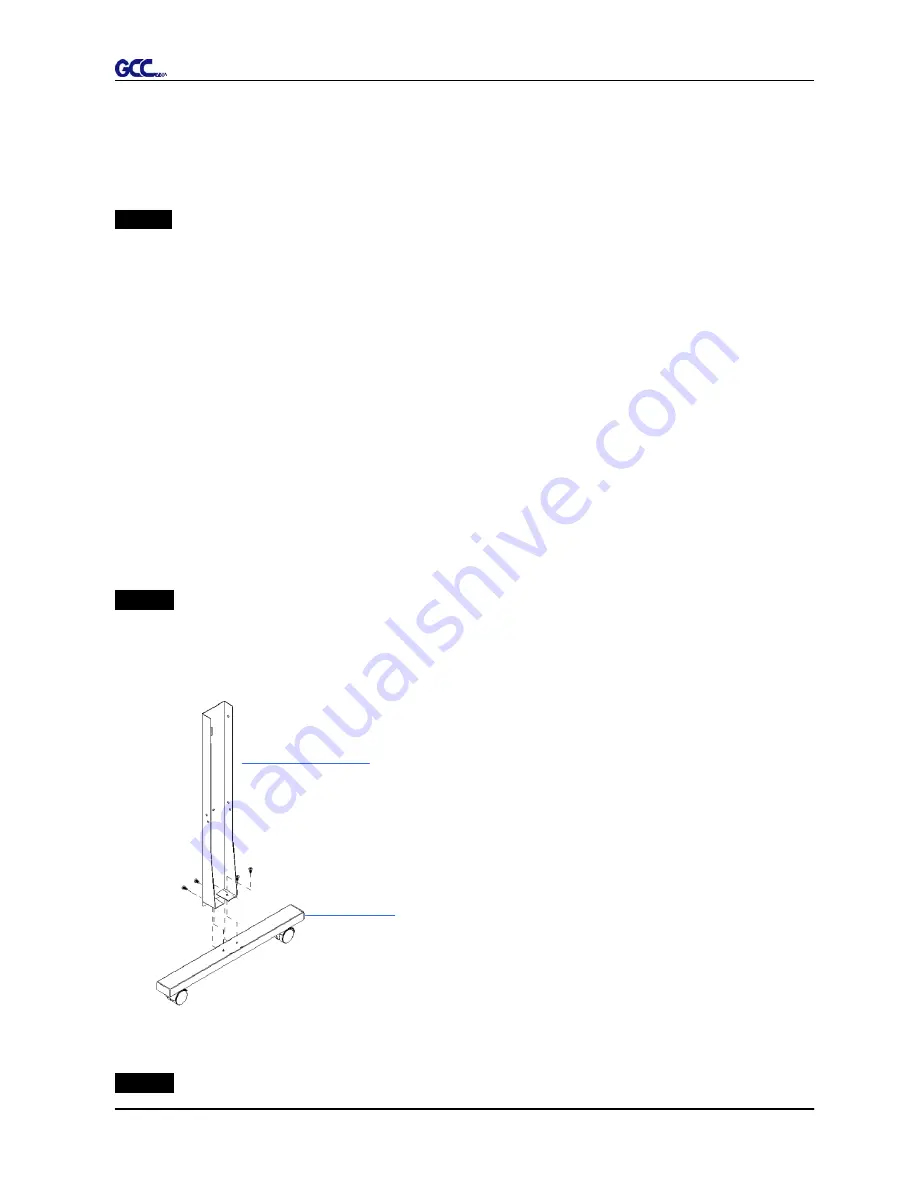
 

Step 2   

Position the support for the left side perpendicularly to part 

X

and put the screws into the 

holes and tighten them to form a left side T-stand (Figure 2-1). Repeat the same steps with the 
support for the right side.   


Support for left side

X

Bottom Stand with wheels


Figure 2-1 


Step 3   

Summary of Contents for BENGAL

Page 1: ...BENGAL CUTTING PLOTTER User Manual Great Computer Corporation V 2 1 Oct 10...

Page 2: ...y the information contained in this user manual at any time without prior notice un authorised modification copying distribution or display is prohibited All comments queries or suggestions concerning...

Page 3: ...der a blade tip can fly out During an operation do not touch any of the moving parts of this machine such as the carriage Also be careful to make sure that clothing and hair do not get caught Always c...

Page 4: ...2 5 1 USB Interface 2 9 2 5 2 How to switch the USB mode 2 12 2 5 3 RS 232 Interface 2 12 3 Operation 3 1 The Control Panel 3 1 3 2 VLCD 3 3 3 3 File Uploader 3 6 3 4 Data Transmission 3 7 4 Basic Mai...

Page 5: ...ntity Cutting Plotter 1 Set Accessories 1 Set 1 Installation CD 2 AC Power Cord 3 Desktop Support Brackets 4 Cutting Pad 5 USB Cable 6 RS 232 Cable 7 Printer Cable 8 Tweezers 9 Paper Slicer 10 Error C...

Page 6: ...h clear guideline marks D Tool Carriage To help perform cutting job with installed blade or pen E Blade Holder To hold the blade F Platen The surface for holding and supporting media in operation G Cu...

Page 7: ...tor To insert the AC power cord K Fuse 3Amp L Power Switch To turn on or off the machine M USB Connector To connect the machine and a computer through a USB cable N Parallel Connector To connect the m...

Page 8: ...ily from any direction z Keep enough space for the machine accessories and supplies z Keep the working area stable avoiding sever vibration z Keep the temperature between 15 and 30 60 86o F in the wor...

Page 9: ...ght side vertical stand z 1 Support for left side z 1 Support for right side z 1 Stand Beam z 2 Bottom Stands with wheels z 2 Sliding brackets for paper takeup z 1 Hex Wrench M5 4 z 28 Socket flat hea...

Page 10: ...o the holes but do not tighten them at this step Stand Beam T stand Figure 2 2 Step 4 Position both the left Support and right Support perpendicularly to the T stand and put the screws into the holes...

Page 11: ...nder the plotter and insert the screws into the holes on the bottom of the plotter but do not tighten them up as shown in Figure 2 4 Figure 2 4 Step 6 Tighten the screws of step 4 and step 6 Place the...

Page 12: ...tep 2 Install blade Figure 2 7 Push the blade to the bottom of the blade holder Figure 2 8 Figure 2 8 Figure 2 7 Step 3 Adjust the blade tip to suitable length by screwing Blade tip adjustment screw c...

Page 13: ...may need to replace a new one 9 If cutting quality is not as good as usual you may need to replace a new one 9 If the blade is broken you have to replace a new one Tips When to replace a new blade Cau...

Page 14: ...nment rulers on the platen extension will help you to adjust the media precisely Figure 2 13 Figure 2 13 Figure 2 14 Figure 2 15 Step 3 Then move the pinch rollers manually to the proper position Be s...

Page 15: ...a support system or desktop media support system for roll media Please refer to Chapter 2 2 for hardware setup and Chapter 2 4 1 for media loading 2 5 Cable Connection The cutting plotter communicates...

Page 16: ...for driver setup Step 1 Connecting your GCC cutter 1 Connect the USB connector to the machine and then USB driver will installed automatically Caution 9 If you are using Windows 2000 XP Vista 7 as you...

Page 17: ...iver installation depending on the operating system installed on your computer to start the installation The Expert Pro model is used as an illustration in the following steps Click Yes to continue NO...

Page 18: ...d you will see a message below and click on OK upon completion Enjoy your GCC cutter Note 1 If the driver is being installed for a second time the user will be prompted as to whether a second copy of...

Page 19: ...ar button and then press the origin set button to finish your set up B Switching to Common USB mode If you want to switch the USB mode from GCC USB mode to Common USB mode please press the Cut Test bu...

Page 20: ...ode only ON OFF LINE and PAUSE keys activated While in off line mode the settings in VLCD can be adjusted PAUSE To temporarily halt cutting process or to continue REPEAT To repeat last job DATA CLEAR...

Page 21: ...ng the cutting job Note 9 Make sure the machine is in off line mode to enable this function Step 1 After sizing press the ON OFF LINE button to set as off line mode Step 2 Move the carriage to a prefe...

Page 22: ...using the USB cable choose USB0 from the pull down menu If you are using a Serial cable choose either COM1 or COM2 Make sure no other devices are occupying the port that you are going to use 9 If the...

Page 23: ...4 25000mm and the distance between two pinch rollers is 568 85mm Figure Force To adjust the blade force between 0 and 400 Default 80g Media Weight To choose different weights of media in two options...

Page 24: ...smoothing cut function Media Type To choose the media type of Roll media Default or single sheet media pdate Setting U To apply the changed setting onto the cutter by press the Update Setting button...

Page 25: ...3 11 9 This function will be activated while choosing COM port for data transmission Port setup button to pop up the setup window for parameter change Figure 3 3 2 Functions of File Uploader 9 Press t...

Page 26: ...r ttings the data can be transmitted from your application Option 2 M te HP GL or HP GL 2 commands therefore As long as the file is HP GL or HP GL 2 format the cutting plotter can Option 1 With proper...

Page 27: ...free cloth If necessary clean it with a water rinsed or an alcohol rinsed cloth Wipe the cutting plotter to remove any residues on the cutting plotter Finally absorb water with a soft lint free cloth...

Page 28: ...g use a lint free cloth or cotton swab to wipe away the accumulated dust from the rubber portion of the pinch rollers To prevent the pinch rollers from rotating while cleaning use your fingers to hold...

Page 29: ...k the following items first Is the power cord plugged in properly Is the power cord connected to the power connector properly Is the power switch turned on properly Why doesn t the cutting plotter ope...

Page 30: ...ph is clipped This condition indicates that the cutting graph is bigger than the cutting area You can solve the problem by 1 Reload a wider or longer media 2 Move the pinch rollers to widen the cuttin...

Page 31: ...bits 1 stop bit Then press ON OFF Line key to switch back to On Line mode Warning 6 Width sensor error Check that the pinch rollers are positioned above the grid drum and reload the media again In or...

Page 32: ...an obstruction to the carriage relating to a problem on the Y axis Please clear the obstruction and check that the carriage can move smoothly Then turn on the power and reboot the cutting plotter 5 3...

Page 33: ...ce 400g Max Cutting Speed Diagonal 600 mm sec 23 6 sec Software Resolution 0 025 mm Repeatability 0 1mm Buffer Capacity 500 KByte Interfaces USB 1 1 Parallel Serial Commands HP GL HP GL 2 Configurable...

Page 34: ...the file with CorelDRAW User Instructions 1 Open CorelDRAW finish editing all the files you wish to plot and select all the images at once 2 Select Outline Pen to adjust the outline for cutting 3 Adj...

Page 35: ...Bengal User Manual 4 Select File Print to output the file to your cutters 5 Choose the correct model you have installed CorelDRAW Plug In A 3...

Page 36: ...eposition images to Bottom left corner Please note that you must put your image at the bottom left corner 7 Go back to the General page and check that your image is at the bottom left corner Click Pri...

Page 37: ...pacity 500 KByte Interfaces USB 1 1 Parallel Serial Commands HP GL HP GL 2 Configurable Origin Yes Control Panel 6 LEDs 10 Keys Stand Optional Temperature 15 C 30 C 60 F 86 F Operation Environment Hum...

Page 38: ...ffset For cutting reflective vinyl cardboard sandblast flock and stencil sharp edge 26500058G The blade is 60 with Green Cap 0 50 mm blade offset For cutting thin sandblast mask and stencil with frict...

Page 39: ...to the reference point OFFSET is the distance that the blade tip is displaced from the centerline of the blade Protrusion Length of the Blade Length of protrusion t1 t 2 2 but for your convenience yo...

Reviews:

Related manuals for BENGAL