GBC AdvancedPunch Pro
08/20/2015
Repairs/Adjustments
4-33
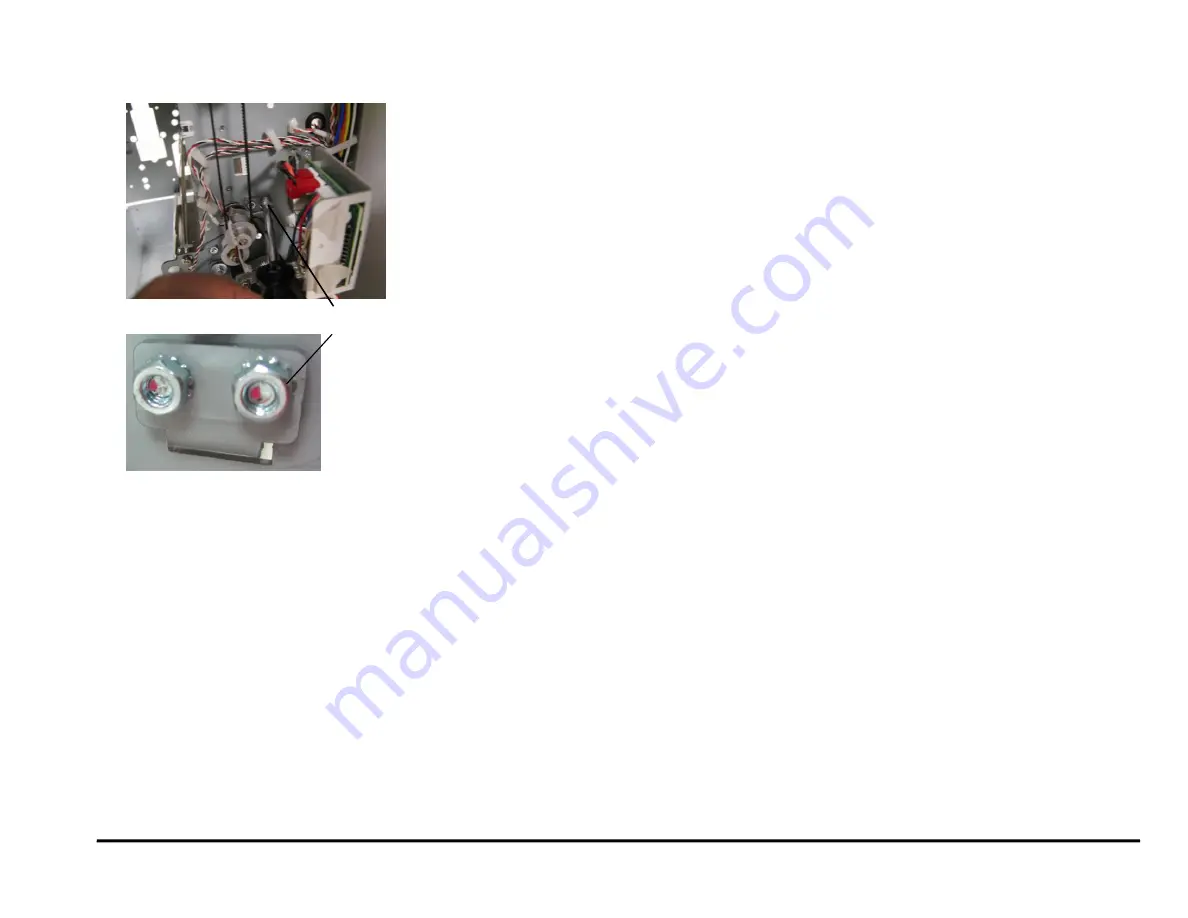
17. If you cannot remove the Entrance Drive Panel, remove the Idler
Panel Mount Bracket from the lower position only.
18. Remove the Entrance Drive Panel.
19. Transfer the sensor Boards and the Clear Cover Sensor to the new
Panel Weldment.
Installation Procedure
Do the following to install the Entrance Drive Panel.
1. Place the Entrance Drive Panel in position.
2. Install the Idler Panel Mount Bracket at the lower position with (2) M4
nuts.
3. Install the Screws (5) that hold the Entrance Drive Panel to the rear
Frame.
4. Install the Screws (5) that hold the Entrance Drive Panel to the front
Frame.
5. Connect the Sensor Board Connectors (2).
6. Place the Sensor Cables in the Cable Clamps and close the Cable
Clamps.
7. Do REP 2.22.1 to install the Drive Roller for Roller N5.
8. Hook the Acceleration Panel Latch Springs (2) to the Idler Panel side.
9.
Do REP 2.3 to install the Acceleration Idler Roller Panel.
10. Do REP 2.2 to install the Entrance Idler Panel.
11. Do REP 1.18 to install the Docking Bracket.
12. Do REP 1.8 to install the Side Cover.
13. Do REP 3.1 to install the Punch Module.
14. Do ADJ 1.8 Drive Panel Position Adjustment.
15. Do REP 1.6 to install the Rear Cover.
16. Connect the Power Cord.
17. Power ON the entire printing system.
Idler Panel Mount Bracket
Summary of Contents for AdvancedPunch Pro
Page 26: ...Service Call Procedures 08 20 2015 GBC AdvancedPunch Pro 1 8 Notes ...
Page 28: ...GBC AdvancedPunch Pro 11 07 2018 RAPS 2 2 ...
Page 78: ...Punch Quality 11 07 2018 GBC AdvancedPunch Pro 3 2 This page intentionally left blank ...
Page 230: ...Repairs Adjustments 08 20 2015 GBC AdvancedPunch Pro 4 142 Notes ...
Page 263: ...GBC AdvancedPunch Pro 09 11 2018 Parts List 5 33 PL 6 4 Wiring Drawing OEM Configurations ...
Page 264: ...Parts List 09 11 2018 GBC AdvancedPunch Pro 5 34 PL 6 5 Wiring Drawing DFA Configurations ...
Page 360: ...General Procedures and Information 09 11 2018 GBC AdvancedPunch Pro 6 90 Notes ...
Page 362: ...Wiring Data 08 20 2015 GBC AdvancedPunch Pro 7 2 This page intentionally left blank ...
Page 363: ...GBC AdvancedPunch Pro 08 20 2015 Wiring Data 7 3 System Wiring ...
Page 364: ...Wiring Data 08 20 2015 GBC AdvancedPunch Pro 7 4 System Wiring DFA Configurations ...
Page 365: ...GBC AdvancedPunch Pro 08 20 2015 Wiring Data 7 5 Plug Jack Connectors ...
Page 366: ...Wiring Data 08 20 2015 GBC AdvancedPunch Pro 7 6 Plug Jack Connectors DFA Configurations ...
Page 367: ...GBC AdvancedPunch Pro 08 20 2015 Wiring Data 7 7 Notes ...
Page 368: ...GBC AdvancedPunch Pro 08 20 2015 Installation Instructions 8 1 8 Installation Instructions ...
Page 369: ...Installation Instructions 08 20 2015 GBC AdvancedPunch Pro 8 2 ...
Page 370: ...GBC AdvancedPunch Pro 08 20 2015 Installation Instructions 8 3 ...
Page 371: ...Installation Instructions 08 20 2015 GBC AdvancedPunch Pro 8 4 ...
Page 372: ...GBC AdvancedPunch Pro 08 20 2015 Installation Instructions 8 5 ...
Page 373: ...Installation Instructions 08 20 2015 GBC AdvancedPunch Pro 8 6 ...
Page 374: ...GBC AdvancedPunch Pro 08 20 2015 Installation Instructions 8 7 ...
Page 375: ...Installation Instructions 08 20 2015 GBC AdvancedPunch Pro 8 8 ...
Page 376: ...GBC AdvancedPunch Pro 08 20 2015 Installation Instructions 8 9 ...
Page 377: ...Installation Instructions 08 20 2015 GBC AdvancedPunch Pro 8 10 ...
Page 378: ...GBC AdvancedPunch Pro 08 20 2015 Installation Instructions 8 11 ...
Page 379: ...Installation Instructions 08 20 2015 GBC AdvancedPunch Pro 8 12 ...
Page 380: ...GBC AdvancedPunch Pro 08 20 2015 Installation Instructions 8 13 ...
Page 381: ...Installation Instructions 08 20 2015 GBC AdvancedPunch Pro 8 14 ...


