CHAPTER 4: Installing Components
www.gateway.com
36
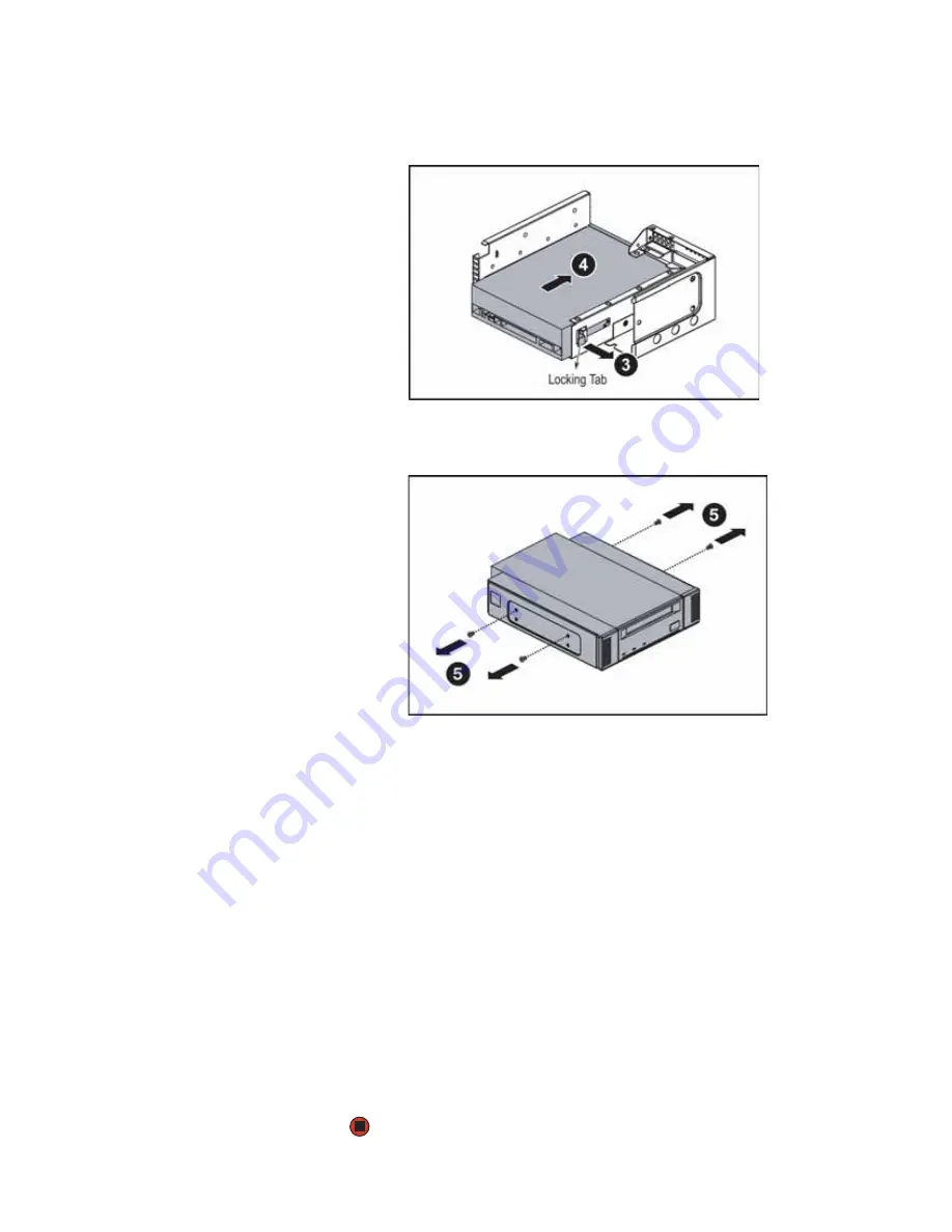
7
Lift the locking tab (3) on the back of the tape drive tray, then push the
tape drive (4) and tape drive bracket out of the tray.
8
Unscrew the four mounting screws (5) holding the tape drive in the tape
drive bracket, then lift the tape drive out of the bracket.
9
Put the new tape drive into the drive bracket and secure with the four
screws you removed previously (if you are installing a new tape drive, the
screws and bracket are included with the tape drive installation kit).
10
Push the new tape drive and drive bracket into the tape drive tray, then
push down the locking tab.
11
Insert the media cage into the assembly bay in the chassis.
12
Secure the assembly by tightening the thumbscrew you previously
loosened.
13
Connect the data and power cables to the back of the tape drive.
14
Reinstall the large fan cage by following the instructions in
.
15
Follow the instructions in
“Closing the server case” on page 32
16
Reinstall the bezel, if required, by snapping it into place on the front of
the chassis.
17
Reconnect all power cords and peripheral device cables, then turn on the
server.
Summary of Contents for E-9525R
Page 1: ...USER GUIDE Gateway E 9525R Server ...
Page 2: ......
Page 6: ...Contents www gateway com iv ...
Page 70: ...CHAPTER 4 Installing Components www gateway com 64 ...
Page 107: ...APPENDIX B 101 BIOSSettings ...
Page 118: ...APPENDIX B BIOS Settings www gateway com 112 ...
Page 119: ...APPENDIX C 113 Safety Regulatory and Legal Information ...
Page 128: ...Index www gateway com 122 user password 24 W Web site Gateway 10 ...
Page 129: ......
Page 130: ...A MAN E 9525R USR GDE R0 10 06 ...


