background image

84     Maintaining and Troubleshooting the Gateway ALR 7200 Server

Video Problems

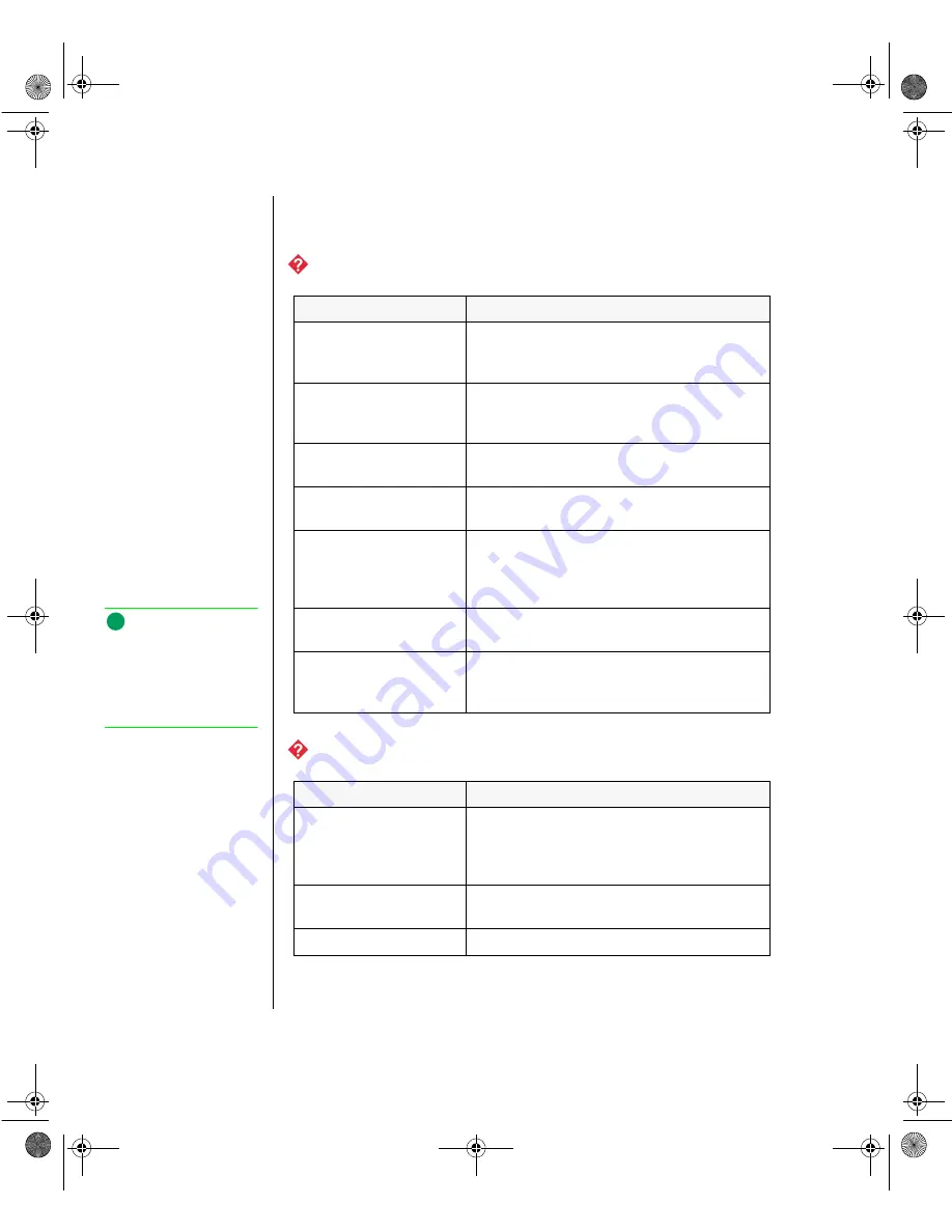
The system is running but there is no display.

The text on the display is dim or difficult to read.

Probable Cause

Solution

The monitor is not 
turned on.

Make certain the monitor is plugged in and 
turned on. If power is applied to the monitor, 
the green power LED should illuminate. 

The monitor’s data 
cable is not connected.

Make certain the monitor’s data cable is 
connected to the video controller on the back 
of the system. 

The connector or cable 
is damaged.

Check the connector and cable for bent or 
damaged pins. 

The monitor is 
defective.

Connect a working monitor to the computer.

The monitor’s 
brightness and contrast 
controls are turned 
down.

Adjust the brightness and contrast knobs to 
the center position.

The video card is not 
seated correctly.

Open the system and reseat the video card. 

The video card is not 
compatible with the 
system.

PCI video cards must be compatible with the 
system.

Probable Cause

Solution

The monitor’s 
brightness and contrast 
controls are turned 
down.

Adjust the brightness and contrast knobs until 
the text becomes clear.

Sunlight is glaring off 
the display.

Position the monitor away from the sun or 
window.

The CRT may be old.

Replace the monitor.

 Note:

Your system board may 
have a built-in video 
adapter, so there may not 
be a video adapter to 
remove and replace.

3436.book  Page 84  Friday, August 7, 1998  10:23 AM

Summary of Contents for ALR 7200

Page 1: ...7200 TECH REF R1 7 98 In our effort to use nature s resources efficiently and wisely we print all manuals on recycled papers that meet the minimum requirements established by the Federal EPA in its g...

Page 2: ...ateway 2000 Inc Intel Intel Inside logo and Pentium are registered trademarks and MMX is a trademark of Intel Corporation Microsoft MS MS DOS and Windows are trademarks or registered trademarks of Mic...

Page 3: ...over 7 Chapter 2 Components 9 System Board Components 10 Chassis Fans 11 Power Connectors 11 Drive Controllers and Connectors 12 Front Panel Connectors 13 Server Management Connectors 14 System Jumper...

Page 4: ...en 61 Boot Menu Screen 62 Exit Menu Screen 64 Updating the BIOS 65 Chapter 5 Troubleshooting 67 Introduction 68 Important Safety Instructions 69 Computer Virus Notice 70 Viruses 70 Types of Viruses 70...

Page 5: ...ry Map 93 I O Map 94 IRQ Usage 95 DMA Usage 96 Appendix B Regulatory Compliance Statements 97 FCC Notice 98 Industry Canada Notice 99 CE Notice 99 VCCI Notice 100 Australia New Zealand Notice 100 Inde...

Page 6: ...vi Maintaining and Troubleshooting the Gateway ALR 7200 Server 3436 book Page vi Friday August 7 1998 10 23 AM...

Page 7: ...Preface Contents About This Guide viii Conventions Used in This Guide ix 3436 book Page vii Friday August 7 1998 10 23 AM...

Page 8: ...omponents covers information on maintaining replacing and upgrading the components in the system This section includes information about options for the system and installation instructions Chapter 3...

Page 9: ...EL A plus sign indicates that the keys must be pressed simultaneously Setup Commands to be entered options to select and messages that appear on your monitor are printed in bold User s Guide Names of...

Page 10: ...x Maintaining and Troubleshooting the Gateway ALR 7200 Server 3436 book Page x Friday August 7 1998 10 23 AM...

Page 11: ...autions 2 Opening the System 3 Removing the Top Cover 3 Removing the Side Covers 4 Removing the Bezel 4 Closing the System 6 Reinstalling the Bezel 6 Reinstalling the Side Covers 6 Reinstalling the To...

Page 12: ...ve the system case cover Static Electricity Precautions Avoid static causing surfaces such as plastic and styrofoam in your work area Remove the parts from their antistatic bags only when you are read...

Page 13: ...tion Removing the Top Cover 1 Remove the three screws located on the rear of the system 2 Slide the top cover back then pull the cover up 3 Set the cover aside Figure 1 Removing the Top and Side Cover...

Page 14: ...on the previous page 3 Slide the side cover back then pull the cover off 4 Set the cover aside 5 Repeat steps 2 4 for the right side cover Removing the Bezel 1 Disconnect the power cord Unlock the bez...

Page 15: ...of the chassis remove the two screws securing the bezel to the chassis Figure 2 Removing the Bezel 5 Holding onto the bottom handle firmly pull bezel away from chassis 6 Set the bezel aside 3436 book...

Page 16: ...at the bezel pegs are aligned with the mount holes on the front of the chassis 2 Secure the bezel with the screws you removed when removing the bezel Reinstalling the Side Covers 1 Align the side cove...

Page 17: ...ing the system 4 Repeat for the other side cover Reinstalling the Top Cover 1 Align the top cover with the ledges on the chassis 2 Slide the cover toward the front of the unit 3 Secure the cover with...

Page 18: ...8 Maintaining and Troubleshooting the Gateway ALR 7200 Server 3436 book Page 8 Friday August 7 1998 10 23 AM...

Page 19: ...ans 11 Power Connectors 11 Drive Controllers and Connectors 12 Front Panel Connectors 13 Server Management Connectors 14 System Jumpers 15 Battery 15 Expansion Slots 16 I O Connectors 16 Processor Sub...

Page 20: ...e 4 Figure 4 System Board A Chassis Fan Connector B Power Connectors C Soft Power Connector D Chassis Fan Connector E Secondary IDE Connector F Primary IDE Connector G Floppy Connector H Reset Connect...

Page 21: ...aker Connector R External Boot ROM Connector S External I2 C Connector T SCSI B Connector U SCSI A Connector V Clear CMOS Jumper W Battery X ISA Slot 1 Shared with Secondary PCI Slot 4 Y Secondary PCI...

Page 22: ...re Ultra DMA compliant while maintaining support for IDE devices that do not support the Ultra DMA specification Floppy Controller and Connector The floppy drive controller and connector on the system...

Page 23: ...are several connectors that provide connection of the front panel features to the system board Some of these connectors are redundant allowing the front panel features to vary according to the system...

Page 24: ...ds that contain a separate boot ROM and require separate access to the system board LED Display Connector Connects the LEDs on the front cover to the system board Server Management Connectors The serv...

Page 25: ...ses changing the settings of reserved jumpers can cause damage to the system board Clear CMOS Jumper This jumper allows you to clear the CMOS memory You should only do this if you cannot access the no...

Page 26: ...k cover of the system Figure 5 shows the connectors and the table below provides a key to the figure Figure 5 I O Connectors The following I O connectors are included with the system Two universal ser...

Page 27: ...ernet connector with two LED indicators The green LED indicates a communication link has been established with the network and the yellow indicator shows that the communication is occurring at 100 Mbp...

Page 28: ...eatsink includes a fan connect it to the correct fan connector Voltage Regulator Modules Each CPU must have a dedicated voltage regulator module VRM which adjusts the voltage supplied to the CPU The V...

Page 29: ...e Jumpers 25 Processor Speed Jumper 25 Clear CMOS Jumper 26 Installing Memory and Hardware 27 Installing Memory 27 Adding and Replacing Drives 31 Adding an Expansion Card 38 Replacing the Battery 40 I...

Page 30: ...e static electricity wrist strap It is critical that a heat sink be installed on each Pentium II processor The Pentium II processor overheats and fails if it is not cooled sufficiently The heat sink p...

Page 31: ...ecure it see Figure 6 Figure 6 Removing the Pentium II Processor 4 Lift the cartridge up and away from the system board 5 Place the processor cartridge that you removed in a safe place 6 Remove the re...

Page 32: ...nk attached to it attach the heatsink according to the instructions that came with the processor upgrade kit 9 Replace the lock bar on the processor support and secure it with the two screws that you...

Page 33: ...sink be installed on each Pentium II processor The Pentium II processor overheats and fails if it is not cooled sufficiently The heat sink provided with the Pentium II processor on the system provide...

Page 34: ...gure 9 Installing the Pentium II Processor 5 Place the lock bar on top of the supports and secure it by inserting and tightening the two screws 6 Set the jumpers for the new processor configuration se...

Page 35: ...d to change jumper settings The Processor Speed jumper JP22 configuration block lets you set the processor speed The system automatically detects the bus speed supported by the processor and uses the...

Page 36: ...configuration settings for later reference 3 Turn off the system and disconnect the power cord 4 Open the case observing the static electricity precautions in Chapter 1 5 Move the jumper shunt on the...

Page 37: ...e this information is automatically detected by the BIOS Refer to the DIMM configuration chart later in this section for valid memory configurations You may select any combination that provides the to...

Page 38: ...automatically locks the socket clamps on each end of the DIMM 6 Close the case as described in Chapter 1 7 Reconnect the power cord and turn on the system 1 Gently push out the plastic socket clamps o...

Page 39: ...Installing Memory and Hardware 29 2 Carefully lift the DIMM out of the socket Figure 13 Removing the DIMM 3 Store the DIMM in a static free container 3436 book Page 29 Friday August 7 1998 10 23 AM...

Page 40: ...B 4x72 32MB 2x72 16MB 2x72 16MB 192 16x72 128MB 8x72 64MB 192 16x72 128MB 4x72 32MB 4x72 32MB 192 16x72 128MB 4x72 32MB 2x72 16MB 2x72 16MB 192 8x72 64MB 8x72 64MB 8x72 64MB 192 8x72 64MB 8x72 64MB 4x...

Page 41: ...Chapter 1 3 Locate the 3 5 inch disk drive 4 Disconnect the power and data cables from the back of the drive noting their location and orientation You will reconnect these cables after you install the...

Page 42: ...4 If no drive is installed in the drive bay remove the metal drive bay cover from the front of the 5 25 inch drive bay Also remove the plastic drive bay cover on the front bezel If you are replacing...

Page 43: ...drive See drive documentation for proper drive jumper settings and cable orientation 12 Close the case as described in Chapter 1 13 Reconnect the power cord and turn on the system 14 The system shoul...

Page 44: ...5 inch bay at the front of the chassis 1 Turn off the system and disconnect the power cord 2 Open the case observing the static electricity precautions in Chapter 1 3 Locate the hard disk assembly ben...

Page 45: ...Disk Bracket 6 Remove the screws that attach the hard drive to the mounting bracket and remove the hard drive 7 Secure the new hard drive to the mounting bracket using the screws you removed in Step...

Page 46: ...to a drive cage which allows the drives to be easily installed and removed from the system chassis This procedure refers to the drives installed in the 3 5 inch drive bay at the front of the chassis...

Page 47: ...ve from its protective cover and install it into the bay using the screws you removed in the previous step 8 Replace the drive cage in the chassis and secure it with the screws you removed in step 5 9...

Page 48: ...have jumpers or switches that set interrupts and I O addresses They come with instructions that explain how to set them to avoid hardware conflicts Follow the instructions carefully Refer to Figure 4...

Page 49: ...end of the card 8 If required connect cables to the card See card documentation for proper jumper settings and cable orientation 9 Close the case as described in Chapter 1 10 Reconnect the power cord...

Page 50: ...he battery is circular and has the positive pole mark on the top 6 Gently pull the battery from its socket and press the new battery in the socket with the positive pole up Be sure you have pressed th...

Page 51: ...nuals Correct any discrepancies Turn off the system remove the cover and verify that all cables inside the case are attached securely Also make sure that the colored cable edges are aligned correctly...

Page 52: ...5 inch disk labeled Integrated Controller UATA files for Win 95 was shipped with your computer You must use this disk to install the USB driver 1 Start the computer 2 Put the 3 5 inch disk labeled Int...

Page 53: ...etup Utility 44 Using the BIOS Setup Utility 45 Main Menu Screen 46 Advanced Menu Screen 50 Security Menu Screen 59 Power Menu Screen 61 Boot Menu Screen 62 Exit Menu Screen 64 Updating the BIOS 65 34...

Page 54: ...nded to serve as a guide so that you can make changes to your system s BIOS when necessary Many of the screen examples that you will see in this chapter are identical to what you see on your monitor h...

Page 55: ...This item is only usable in a submenu Back Press ESC to back out of any field Next and Previous Item Press the up arrow or down arrow keys to move to the next or previous menu item Select Menu Use th...

Page 56: ...drive installed as drive A The options are 360 kB 5 1 2 MB 5 720 kB 3 1 44 1 25 MB 3 2 88 MB 3 Not installed and Disabled Legacy Diskette B allows you to select the type of diskette drive installed a...

Page 57: ...the secondary master hard disk drive Details of this screen are provided in the section Hard Disk Drive Setup Screen on page 48 Secondary Slave opens the Secondary Slave screen to permit you to setup...

Page 58: ...of a set of previously defined drive types and sizes These values only apply to older drives generally less than 200 MB in size User selecting this option brings up a sub menu where you can enter the...

Page 59: ...rol enabling this option causes Logical Block Addressing to be used in place of Cylinders Heads and Sectors The options are Enabled and Disabled 32 Bit I O enabling this option allows 32 bit communica...

Page 60: ...system is compatible with Plug and Play The options are Yes and No Reset Configuration Data selecting Yes causes the system to clear its configuration data and automatically configure all PnP devices...

Page 61: ...mory Screen on page 58 Advanced Chipset Control opens the advanced chipset control screen which contains a single field The field is ECC Config which allows you to set the extent of error checking and...

Page 62: ...mory Reservation screen This screen allows the user to reserve blocks of upper memory for use by legacy ISA devices Details of this screen are provided in the section Memory Reservation Screen on page...

Page 63: ...cted from the resource configuration screen It allows you to reserve a block of memory for ISA devices Figure 23 Memory Reservation Screen XXXX XXXX the specified area of upper memory may be reserved...

Page 64: ...enever you select IRQ Reservation from the advanced menu screen It allows you to manually reserve IRQs for specific devices Figure 24 IRQ Reservation Screen IRQx the specified IRQ may be reserved for...

Page 65: ...optional addresses available Interrupt displays the current interrupt for integrated Serial Port A Using the or key displays the optional addresses available Serial Port B options include Enabled Dis...

Page 66: ...ng the or key displays the optional addresses available Interrupt displays the current interrupt for the integrated Parallel Port Using the or key displays the optional addresses available DMA Channel...

Page 67: ...y Click options are Enabled and Disabled Enable causes an audible click when each key is pressed Keyboard Auto Repeat Rate determines the rate at which a character repeats if a key is held down Option...

Page 68: ...System BIOS Area controls the caching of the system BIOS area Options are Uncached or Write Protect Cache Video BIOS Area controls the caching of the video BIOS area Options are Uncached or Write Prot...

Page 69: ...or Disabled Security Menu Screen This screen allows you to set system security characteristics Figure 28 Security Menu Screen Supervisor Password displays status of administrative password Options are...

Page 70: ...rify the password used to control access to the system at boot If the user password has already been set you must enter the current password before you are able to enter and verify the new password Pa...

Page 71: ...tem Standby Timer opens a menu in which you can select the amount of time before the system enters its power down state Auto Suspend Timeout opens a menu in which you can select the number of PCI cloc...

Page 72: ...ot Device designates the device that the system polls first upon boot up Options include Diskette Drive Hard Drive Removable Devices ATAPI CD ROM Drive and Network Boot Second Boot Device designates t...

Page 73: ...hard drives The system attempts to boot to the operating system from the first hard drive on this list If no operating system is found the system tries the next drive listed until an operating system...

Page 74: ...ings you have entered The next time you boot the system the BIOS configures your system using the old settings Load Setup Defaults displays the setup defaults in cases where the settings have been cor...

Page 75: ...e contents of the BIOS file you downloaded and copy the contents onto a bootable disk 6 Place the bootable disk containing the BIOS files into drive A and restart the system with the disk in the drive...

Page 76: ...this process If you do not set the CMOS values back to the correct values the system may function erratically Note You may encounter a CMOS checksum error or other problem after the system restarts Tr...

Page 77: ...ing Your System 71 Virus Prevention 71 Troubleshooting Checklist 73 Verifying Your Configuration 73 Troubleshooting Guidelines 73 CD ROM Problems 74 Hard Disk Problems 76 Memory Processor Problems 77...

Page 78: ...ror occurs within an application consult the documentation supplied with the software This section identifies solutions to common problems If the suggestions in this chapter do not resolve your proble...

Page 79: ...cord or allow anything to rest on it If you use an extension cord with this system make sure the total ampere ratings on the products plugged into the extension cord do not exceed the extension cord a...

Page 80: ...iruses infect macro files of programs such as word processing and spreadsheet programs Boot viruses attach themselves to a boot record master boot FAT or partition table Multipartite viruses are both...

Page 81: ...program Next reboot your system as follows shut the system down then turn it off for at least 15 seconds before turning it back on This is the only way to ensure the virus does not remain in your syst...

Page 82: ...t before shipping Unfortunately today s technology makes the creation of newer viruses possible some of which can elude even the best scanners available Hence there is no absolute guarantee of virus i...

Page 83: ...ever remove the system cover while the system is turned on Do not attempt to open the monitor it is extremely dangerous Even if the monitor s power is disconnected stored energy within the monitor s c...

Page 84: ...tem and then reseat the sound card Make certain the cables are connected properly The speakers may be faulty Connect a set of headphones to the speaker jack to test the output If they work replace the...

Page 85: ...he Peripheral Configuration Advanced menu set the Secondary IDE Interface to Auto and make certain the Secondary IDE Status is Enabled The CD cables are not installed correctly Open the system and che...

Page 86: ...CSI address Change the device s SCSI address to one that is not currently being used by the system The cables are not connected correctly Open the system and check the cable connections Probable Cause...

Page 87: ...ty chip resides Third party diagnostic programs can help determine which chip or memory segment is failing Probable Cause Solution The processor was installed incorrectly or in the wrong socket Check...

Page 88: ...plugged into the appropriate port on the modem line port The modem is not configured with a valid interrupt or address Check the system settings for possible conflicts If one exists correct the proble...

Page 89: ...les are not installed correctly Open the system and check all cables between the controller and the device Probable Cause Solution The disk drive may be configured incorrectly Restart your computer an...

Page 90: ...operly Open the system and check the cable between the disk drive and its controller Make certain the pins are not bent or misaligned Probable Cause Solution The interrupt and or I O address is set in...

Page 91: ...nter and the system Make certain it is connected to the proper port Check the connector and cable for bent or broken pins The printer is not designated as the default printer If the printer to which y...

Page 92: ...fully plugged into their AC IN connectors on rear of computer Verify both power supplies are set to the correct voltage range 115 V AC or 230 V AC Verify both power supplies are turned on Replace def...

Page 93: ...nected properly Check the cable Make certain it is plugged in correctly The mouse driver did not load when the system booted Load the appropriate mouse driver manually or contact Technical Support The...

Page 94: ...efective Connect a working monitor to the computer The monitor s brightness and contrast controls are turned down Adjust the brightness and contrast knobs to the center position The video card is not...

Page 95: ...wires The video card has failed Try another video card The display setup is incorrect From the Control Panel window Start Settings ControlPanel double click Display and check the settings The correct...

Page 96: ...from sources of electrical interference such as televisions unshielded speakers microwaves fluorescent lights and metal beams or shelves The monitor needs to be degaussed Turn off the computer and mon...

Page 97: ...urn to Windows type exit and press ENTER Base memory xxx expansion This is an informational message only No action is required Checking RAM on disk controller Your BIOS configuration is incorrect Ente...

Page 98: ...select either AT or XT Hard disk controller failure Make certain the hard disk cable is properly connected Open the BIOS Setup program and verify that the correct drive type is selected Hard disk cont...

Page 99: ...ting to AT Replace the keyboard chip Keyboard controller failure Try a working keyboard Make certain the keyboard is compatible with the system You may have to change the switch setting to AT Replace...

Page 100: ...sending another print job If you receive this error often you need to add memory to the printer Printer is out of paper Add paper to the printer Make certain the printer is online Required parameter...

Page 101: ...Appendix A Reference Data Contents Specifications 92 Memory Map 93 I O Map 94 IRQ Usage 95 DMA Usage 96 3436 book Page 91 Friday August 7 1998 10 23 AM...

Page 102: ...ard SCSI controller and a full complement of I O ports Dimensions 17 5 H x 9 25 W x 17 5 D 35 lbs Processor Intel Pentium II processor Processor speed 266 300 333 350 or 400 MHz Processor upgrade Slot...

Page 103: ...apters 896 KB 1024 KB 1 MB 000E 0000 000F FFFF 128 KB System BIOS ROM Above 1 MB 1 MB 16 MB 0010 0000 00FF FFFF 15 MB Extended Memory 15 MB 16 MB 00FE 0000 00FF FFFF 64 KB Mapped RAM or ROM Above 16 M...

Page 104: ...byte Programmable interval timer 2 0049 1 byte Reserved 004A 1 byte CPU speed control counter 2 004B 1 byte Command mode register 0061 0070 16 bytes NMI status registers 0080 008F 16 bytes DMA page r...

Page 105: ...Q Resource NMI 0 System Timer 1 Keyboard 2 Cascade 3 Serial port 2 COM2 4 Serial port 1 COM1 5 Secondary Parallel Port LPT2 6 Floppy Controller 7 Primary Parallel Port LPT1 8 Real Time Clock RTC 9 Cas...

Page 106: ...ts the direct memory access DMA channels that the system typically uses and which ones are available for use by add in devices DMA Resource 0 Cascade 1 Available 2 Floppy Controller 3 Available 4 Redi...

Page 107: ...ppendix B Regulatory Compliance Statements Contents FCC Notice 98 Industry Canada Notice 99 CE Notice 99 VCCI Notice 100 Australia New Zealand Notice 100 3436 book Page 97 Friday August 7 1998 10 23 A...

Page 108: ...does cause interference to radio and television reception which can be determined by turning the equipment off and on the user is encouraged to try to correct the interference by one or more of the f...

Page 109: ...Canada Attention Couper le courant avant l entretien CE Notice This Information Technology Equipment has been tested and found to comply with the following European directives i EMC Directive 89 336...

Page 110: ...radio disturbance may arise When such trouble occurs the user may be required to take corrective action Australia New Zealand Notice This device has been tested and found to comply with the limits for...

Page 111: ...field 58 Cache C800 CBFF field 59 Cache CC00 CFFF field 59 Cache D000 D3FF field 59 Cache D400 D7FF field 59 Cache D800 DBFF field 59 Cache DC00 DFFF field 59 Cache Extended Memory Area field 59 Cache...

Page 112: ...ield Parallel Port 56 Mulit Sector Transfers field 49 Num Lock field 57 Parallel Port field 56 Password on Boot field 60 PCI Bus Monitoring field 61 62 Peripheral Configuration field 51 screen 55 Plug...

Page 113: ...a Setup utility field 58 CC00 CFFF Setup utility field 53 CD ROM drive installing 32 troubleshooting 74 Chassis fan connectors 11 Checklist troubleshooting 73 Clear CMOS jumper 26 Closing the system 6...

Page 114: ...Boot Sector Setup utility field 60 Flash BIOS updating 65 Floppy Disk Controller Setup utility field 56 Floppy drive controller 12 setting drive A 46 setting drive B 46 write protection 60 Formatting...

Page 115: ...27 map 93 removing DIMMs 28 supported 18 troubleshooting 77 Memory Cache Setup utility field 58 Memory Reservation Setup screen 53 Setup utility field 52 Mode Parallel Port Setup utility field 56 Mod...

Page 116: ...ce Configuration Setup screen 52 Setup utility field 51 Resources DMA usage 96 IRQ usage 95 memory usage 93 S Safety static electricity precautions 2 Save Changes Setup utility field 64 SCAM for Windo...

Page 117: ...carding Changes 64 Exit Saving Changes 64 Extended Memory 47 Fifth Boot Device 63 First Boot Device 62 Fixed Disk Boot Sector 60 Floppy Disk Controller 56 floppy drive A 46 floppy drive B 46 Fourth Bo...

Page 118: ...creen 53 peripheral configuration screen 55 power menu screen 61 primary master setup screen 48 primary slave setup screen 48 resource configuration screen 52 secondary master setup screen 48 secondar...

Page 119: ...sor 77 SCSI device 79 system wide problems 82 video 84 Type Setup utility field 48 U Ultra DMA Mode Setup utility field 49 UltraDMA controller 12 UltraSCSI controller 12 Updating BIOS 65 USB driver in...

Page 120: ...110 Maintaining and Troubleshooting the ALR 7200 3436 book Page 110 Friday August 7 1998 10 23 AM...

Page 121: ...NOTES 3436 book Page cxi Friday August 7 1998 10 23 AM...

Page 122: ...8503436 R1 3436 book Page cxii Friday August 7 1998 10 23 AM...

Reviews: