


4 – Mapping Basics
T1 CrossConnect Installation & Operation Manual
Version 2
GatesAir
4-5
Intraplex Products
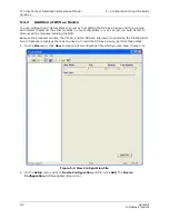
Figure 4-3. IntraGuide Map for Loopback Configuration
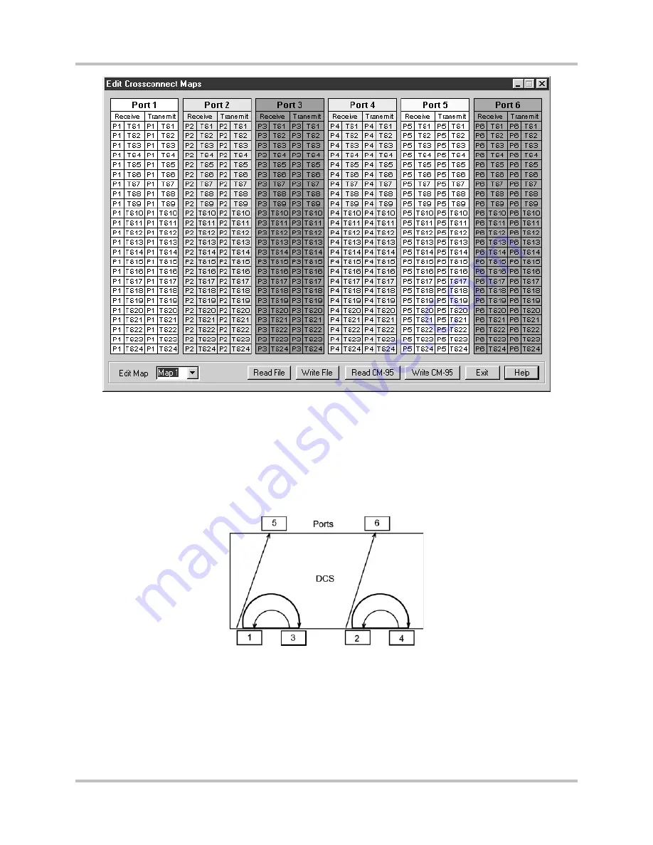
4.5 Pass-through Configuration Mapping
In this example of a pass-through configuration (Figure 4-4), signals are sent from one port and
received by another in a duplex transmission. There are duplex transmissions between ports 1 and 3
and ports 2 and 4, and unidirectional traffic from port 1 to port 5 and from port 2 to port 6. This also
demonstrates multi-drop or broadcast operation since the signal received on port 1 is transmitted on
ports 3 and 5 and the signal received on port 2 is transmitted on ports 4 and 6.
Figure 4-4. Pass-through Configuration
Map 0 for the pass-through configuration in ISiCL (Table 4-4) shows (from top to bottom) all the time
slots from
●
Port 3 mapping to the same time slots on port 1
●
Port 4 mapping to the same time slots on port 2
●
Port 1 mapping to the same time slots on port 3
●
Port 2 mapping to the same time slots on port 4
Summary of Contents for Intraplex T1 DCS-9530 CrossConnect System
Page 2: ......