


T1 CrossConnect Installation & Operation Manual
3 – Installation & Wiring
Version 2
3-6
GatesAir
Intraplex Products
3.4.1
T1 Circuit Wiring
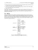
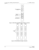
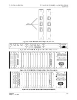
For the DCS-9500 and DCS-9530, wire the T1 ports to the desired T1 circuits. For a DCS-9560 DB-15
system, wire the T1 connectors on the MA-216 to the desired T1 port on the MA-255A using the
provided DB-15 cable and then wire the remaining T1 ports to the desired T1 circuits. For a DCS-9560
RJ-45 equipped system, wire the T1 connectors on the MA-216 to the desired T1 port on the MA-255C
using the provided adapter (DB-15 to RJ-45) and cable and then wire the remaining T1 ports to the
desired T1 circuits.
If you do not have the provided cables, Tables 3-1 through 3-3 list the pin assignments to make your
own. Table 3-1 lists the pin assignments for the MA-216 and MA-255A T1 port. Table 3-2 lists the pin
assignments for the MA-255C T1 port. Table 3-3 lists the pin assignments for the MA-216 and MA-
255C T1 port.
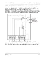
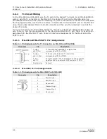
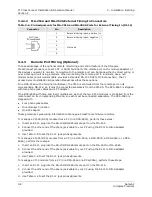
3.4.1.1 MA-216 and MA-255A T1 Port Assignments
Table 3-1. Pin Assignments for T1 Connector on MA-216 and MA-255A
Connector
Pin
Description
1 (ring)
and 9 (tip)
T1 Transmit; the balanced T1 output of the
corresponding CM-5 or DCS-6
3 (ring)
and 11 (tip)
T1 Receive; the balanced T1 input of the
corresponding CM-5 or DCS-6
2, 4, 8,
and 10
T1 signal grounds. These pins may be used to provide
signal ground to an external DCE such as a T1 CSU
All other pins
Not used
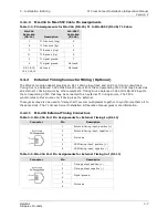
3.4.1.2 MA-255C T1 Port Assignments
Table 3-2. Pin Assignments for MA-255C Ports (RJ-48C)
Connector
Pin
Description
1
Receive tip 1
2
Receive ring 1
3
No connect
4
Transmit ring 1
5
Transmit tip 1
6-8
No connect
Summary of Contents for Intraplex T1 DCS-9530 CrossConnect System
Page 2: ......