background image

DEEP EPIC Setup 

Page 16 


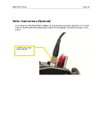
Plug in the optional Submersible Mic, Hydrophone, or Comm input to Mic-1 or Mic-2 
locations on the EPIC / Scarlet cameras 


Fully insert and secure the camera.

  Slide the assembly forward until it stops 

firmly under the thumbscrews.  If there is obstruction, inspect for the reason.  A 
thumbscrew or cable are likely the obstruction.  


Tighten thumbscrews.

  Three thumbscrews secure the EPIC / Scarlet camera to 

the housing.  Tighten by hand, and if desired use the 3/16 hex tool to tighten firmly 
(this is usually not necessary).   


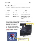
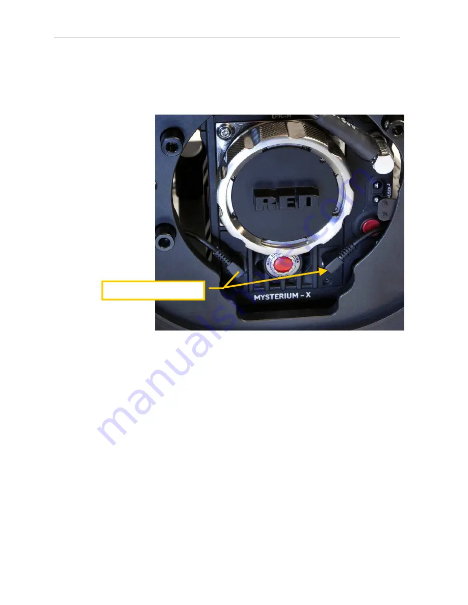
SYNC / CTRL Connections.

  Plug in the SYNC and CTRL connectors to the 

corresponding ports on the camera.  These are clearly marked  as shown in the 
photos.  

  CAUTION: SYNC / CTRL CONNECTIONS.  

Failure to properly connect the SYNC / 

CTRL connections may damage your EPIC / Scarlet camera.    


Other Connections.  

Plug in HD-SDI (optional) if installed.


Place the audio connections. 

Summary of Contents for DEEP EPIC

Page 1: ...DEEP EPIC Setup Use and Care Guide ...

Page 2: ...mera Distributors and John Ellerbrock This manual and current revision is available in 8 5 x 11 size and full color at http www gateshousings com documentation html Gates Underwater Products Inc 13685 Stowe Drive Poway California 92064 USA Phone 800 875 1052 toll free in the U S 858 391 0052 outside the U S Fax 858 391 0053 Web GatesHousings com ...

Page 3: ...Connections Optional 29 Video Connections Optional 30 Water Alarm Optional 31 Check Operation 32 Port and Port Extender 33 Housing Closure 34 Seal Check 36 Final Checks 37 4 DEEP EPIC Operation 38 Right Side Controls 38 Left Side Controls 39 Rear Controls 40 Monitor Controls 41 Buoyancy Adjustment 42 Adjustable Handles 45 Port Options 46 Tripod Mount Optional 47 Accessory Mount Locations 48 Lighti...

Page 4: ...TE Cinema grade design Lens choice and control access are just two of the many features designed into DEEP EPIC A R coated glass optics tally light HD SDI surface feed comm inputs and Seal Check are a few of the items any professional will appreciate Warranty Disclaimer DEEP EPIC is a tool that like any tool requires knowledge and understanding to be effective Your responsibility is to learn the p...

Page 5: ... Monitor Shell Hard Sided Rolling Case x 2 Seal Check system Tool Kit with case Various assembly and spare parts for DEEP EPIC including bolts set screws and o rings Spare O Ring Kit Carry Handle Trim Weights quantity dependent on configuration Optional Parts necessary for operation Port Extender s of choice for your lens Port s of choice Dome either glass or acrylic or Flat and shade Port Mask as...

Page 6: ...ssipation SETTINGS SETUP SYSTEM FAN CONTROL Settings are Fan Control MANUAL Record Speed 75 or 100 Standby Speed 75 or 100 Do not block any ventilation openings or obstruct cooling fan airflow The intake is in the front just below the lens and the exhaust is on the top of the camera Keep the vacuum on DEEP EPIC below 6 in Hg Fan Settings Fan Control to MANUAL Record Speed to 75 or 100 Standby Spee...

Page 7: ...p and use of DEEP EPIC It is the user s responsibility to read understand and employ these procedures Failure to do so can result in poor or non operation of DEEP EPIC and may void your warranty Contact Gates if you have questions this manual or using DEEP EPIC REPLACE FAN RED Digital Cinema has issued a warning on page 33 of the EPIC user guide If you have a camera that requires fan replacement y...

Page 8: ...rt Extender TIP Liberal lubrication of the Port o ring allows easy rotation during installation removal Port Extender Remove the Port Extender by removing 4 screws around the perimeter Rotate the port 90 degrees either direction then gently pull forward to remove Note DEEP RED shown Remove 4 screws securing the port extender and remove Pull the Port Extender forward until it clears the gear drive ...

Page 9: ...up on the latch Once released the shell will slide to the rear on the foot rails until free Step 2 Release 3 latches by pressing on the release tab and lifting up Step1 Pull out the Zoom Iris and Power control on the right side Pull out the Assign control on the left side Step 3 Slide the shell back until free from the housing Note If you are opening the shell after a dive secure the monitor to th...

Page 10: ...wrap Connectors Several connectors are bundled together for travel and protection Remove the protective covering and separate the cables Unbundle the connectors from the protective covering Save the covering for later travel use ...

Page 11: ...tors that may be optionally installed to the side away from camera installation Loosen 3 thumbscrews and slide the camera mount to the rear and free of the housing Loosen three thumbscrews and slide the camera tray to the rear and free of the housing Camera Mount removed from DEEP EPIC ...

Page 12: ... The SYNC and CTRL ports must be set for proper interface to DEEP EPIC At this writing for the current firmware release the ports are set as follows GPI SETTINGS SYSTEM GPIO Set Camera Input to General Purpose In GPO SETTINGS SYSTEM GPIO Set Camera Output to General Purpose Out Set Camera Input to General Purpose In Set Camera Output to General Purpose Out ...

Page 13: ...ck any ventilation openings or obstruct cooling fan airflow The intake is in the front just below the lens and the exhaust on the top of the camera Camera Basics Strip down your EPIC Scarlet to the camera body only Remove all accessories battery drive and lens and other accessories Fan Settings Fan Control to MANUAL Record Speed to 75 or 100 Standby Speed to 75 or 100 Remove all accessories and le...

Page 14: ... tight first then finish with a coin or wide bladed screwdriver Tighten firmly Plug in the Power cable Remove the connector caps and plug in the power cable to the EPIC Scarlet camera Place camera to housing Place the Camera Camera Mount assembly onto the Camera Tray as shown in the photo Secure EPIC Scarlet to Camera Mount with two mounting screws Tighten firmly Plug in the power cable to the cam...

Page 15: ...into the housing This is a good point to connect the LCD cable on the front of the EPIC Scarlet camera See the subsequent sections on installing the RED 5 6 in or RED PRO 5 in external monitor shells to the housing Slide the EPIC Scarlet camera forward and plug in the LCD Connector Top View of LCD Connector ...

Page 16: ...tion Tighten thumbscrews Three thumbscrews secure the EPIC Scarlet camera to the housing Tighten by hand and if desired use the 3 16 hex tool to tighten firmly this is usually not necessary SYNC CTRL Connections Plug in the SYNC and CTRL connectors to the corresponding ports on the camera These are clearly marked as shown in the photos CAUTION SYNC CTRL CONNECTIONS Failure to properly connect the ...

Page 17: ...with the 3 16 ball drive or 3 16 stub length hex key tools Slide the EPIC Scarlet camera fully forward until it stops and the camera mount is visually aligned with the camera mounts Tilt the housing forward and plug in the SYNC and CTRL Connections The connectors are clearly marked Plug in the optional HD SDI connector if installed ...

Page 18: ...ll a charged REDBRICK battery The red LED just above the EPIC Scarlet record button will verify power is available to the camera Mount lens Mount the lens you plan to use at this time Insert the Power connector here on the side of the V Lock battery mount Install a charged battery Mount the lens to the EPIC Scarlet camera ...

Page 19: ...a current cross reference Secure Guide Bars Insert the guide bars by threading them into the front bulkhead Tighten firmly by hand no tools are required but wrench flats are provided on the guide bars should this be necessary Install Drive Shafts These are black delrin and have a flat spot milled into one end This end inserts into the drive coupler at the face of the front bulkhead Secure gently w...

Page 20: ...l properly aligned and the drive shaft gear hub is centered with the LGD bracket see photo Tighten the two pivot screws gently to secure it in position Step 3 Firmly tighten the screw that couples the drive gear hub to the drive shaft TIP The gear hub drive shaft coupling acts like a clutch the drive shaft will slip when reaching the end of travel in either direction Greater tightening the screw w...

Page 21: ... pin on the housing Secure the ring with the two set screws in the knob to retain The indicator rings now display lens settings on the knob during use Verify Operation Once positioned and secured check operation of the Focus and Iris controls They should rotate freely but with slight resistance in both directions and through the entire range of travel If not repeat steps 1 3 In a subsequent sectio...

Page 22: ...DMOTE Cradle The REDMOTE Cradle is secured only by magnets Pull the cradle away from the REDMOTE Controller to separate Install REDmote Insert the REDmote at an angle as shown in the photo It will fully seat into the cradle Secure with the small thumbscrew REDMOTE Controller Parts REDMOTE Controller Panel shown removed from the housing REDMOTE Cradle Mount Screw RDCC REDmote not included Insert th...

Page 23: ...control to the LOCK position to clear the cradle when mating The REDMOTE Panel will mate to the Cradle when bought in proximity to each other The magnetic fasteners will self align and secure them together The REDMOTE Controller fully assembled Reminder this assembly is shown outside the housing for illustration purposes only Do not remove the REDMOTE Controller from the housing Position the power...

Page 24: ...Install the LCD The RED LCD will insert face down against the window with the connector facing the rear Insert the left edge first closest to the wire It should rest inside the shell without obstruction Inspect the o ring As always inspect the o ring for foreign matter Wipe your finger around the silicone o ring to clear away any dirt hair etc DO NOT LUBRICATE the silicone o ring Remove 4 screws t...

Page 25: ... LEMO connection to the camera is accomplished by passing the connector through the bulkhead opening on the right side of the front shell Pass the connector through then tighten the bulkhead connection Lastly plug the connector into the camera LCD port See the section above Camera Lens Installation for detail on connecting to the EPIC Scarlet cameras Pass the right angle connector through the bulk...

Page 26: ...DEEP EPIC Setup Page 26 Pass the cable through up to the mating collar Face the right angle LEMO connector to the rear then tighten the collar until it stops ...

Page 27: ...Clean the LCD screen as well Connector Plug in the LCD connector Be sure it is fully seated to the LCD Install the LCD The RED LCD will insert face down against the window with the connector facing the rear Insert the left edge first as shown in photo It should rest inside the shell without obstruction Remove 3 screws to open the LCD Monitor shell Insert the RED PRO monitor at an angle as shown th...

Page 28: ...ten until there is no visible gap between shells A good indicator is when the orange o ring is no longer visible Plug in the external monitor to the camera The procedure for connecting to the camera is identical to the RED 5 6 in External Monitor in the previous section Inspect the o ring Wipe clean with your finger to remove foreign material DO NOT lubricate orange o rings Close the shell and sec...

Page 29: ...controlled via one screen on the EPIC Scarlet cameras The Submsersible Microphone Hydrophone and Diver Comm will plug into Mic 1 or Mic 2 of the depending on your configuration Adjust the input levels as described in the EPIC and Scarlet manuals SETTINGS AUDIO VIDEO AUDIO INPUT ...

Page 30: ...Connections Optional If you have the HD SDI option installed no special camera setup is required You need only connect the HD SDI surface feed cable to the bulkhead connector as shown in the photo HD SDI Surface Feed cable optional ...

Page 31: ...m can tested anytime by shorting the detection contacts that lead to the water alarm transducer The water detection condition will activate for 6 seconds If the battery is drained the low battery condition will sound The water alarm requires a single 6V battery like Radio Shack model 23 469 or A544 Your battery should be removed when stored e g between dive trips Check the battery prior to every d...

Page 32: ...are smooth and operational Verify Record Stdby Depress the record switch and verify it activates the camera record function and tally light illuminates The record switch is momentary that is depress it for no longer than 2 seconds to activate If this step does not operate properly verify the GPIO port setting as noted in the Camera Preparation section and verify the SYNC and CTRL connectors are fu...

Page 33: ...use damage Install the Port Extender Position the Port Extender over the entire lens LGD s and secure to the front bulkhead with 4 screws Tighten the 4 screws firmly Install the Port Mask If you have need of a port mask to control reflections see subsequent section on this topic install it now It should slip over the front of the lens with just enough tension to remain in place Install the Port Th...

Page 34: ...ary to retract the Zoom Iris and Power controls prior to mating Do no retract the Rec Stdby Control Mate the shell Position the shell at the rear Note the toe on either side toward the front of the shell Rest the toe on the foot rails to guide the shell into position Gently move the shell forward until it mates with the front bulkhead At the rear of the shell are two more feet that will ride on th...

Page 35: ...trol knobs and the gland Refer to photo If you do not have the LGD s installed at this point it will be necessary to hold the shaft coupler at the front bulkhead and keep it from spinning while you mate the controls Mount the monitor Secure the monitor to the top or rear of the main shell as desired and tighten the screws to secure Mate the shells and close latches Inspect the seal line for gaps M...

Page 36: ...vacuum level on the gage Next move the Seal Check hose to the RED PRO monitor Draw a vacuum close within 1 in Hg to that of the main housing Remove and plug the Seal Check fitting on the RED PRO monitor Move the Seal Check hose back to the main DEEP EPIC housing and start the monitoring process Why do this The LCD cable while waterblocked is not air blocked After drawing vacuum on the monitor air ...

Page 37: ...be opened independently NOTE Inspect the monitor cable regularly While it is a durable marine grade cable care must be exercised to avoid cuts or abrasions that could compromise the cable and thus the housing seal Final Checks Visual Inspection Look closely at all seal mates Port Port Extender and main Housing seal for gaps Look over the housing one final time Verify operation As a final check pow...

Page 38: ...l operates by rotation CW for zooming in one direction and CCW for zooming in the opposite direction Record Standby The Rec Stdby control is black and operates with a momentary counterclockwise rotation Power Push in the power control fully to activate the power button on the camera This control may also be used for Rec Stop if necessary Iris The Iris Control operates by rotation in either directi...

Page 39: ... Left Side Controls Focus The Focus control operates with a CW or CCW motion to adjust lens focus Assign Control A movement up or down of the Assign control trigger will activate the camera assignable buttons 1 or 2 Assign Focus ...

Page 40: ...ttons on the face of the REDmote The Power control is green and rotates 90 degrees Move the control from the Lock position to the On position momentarily to activate power Return the control to the Lock position Below the Power control is the Dial control This rotates the ring on the outside of the navigation buttons left right up down Rotate the control either direction ...

Page 41: ...esponding buttons on the top of the LCD To activate the buttons on the RED 5 6 in External Monitor slide the switches toward the shade then release The switch will retract by itself On the RED PRO 5 in Monitor direct depression of the buttons will activate the corresponding buttons on the side of the RED PRO monitor Slide switches activate the functions on the LCD ...

Page 42: ...djust trim weights Internal shell walls The interior sides of the shell have a lock strip for securing weights You can secure up to four 8oz weight to each side for a total of 8 The trim weights will snap and lock onto the strips on the inside wall To remove pull gently at one edge until it releases CAUTION To avoid internal damage DO NOT travel or transport DEEP EPIC with trim weights installed I...

Page 43: ...he main shell has two accessory rails for securing 16 oz weights Two of these can be secured and adjusted forward and aft for trim 4 and 8 oz weights can also be secured here as needed 16 oz trim weights secured to the bottom rails Trim weight secured to the battery mount Use the adhesive locking material in your spare kit to mount the weight here ...

Page 44: ...s three rails used for handles and monitor that can accommodate 4 and 8oz weights Port Extender The top and sides of the Port Extenders can also accept 4 and 8oz weights Trim weights can be mounted on the top accessory rails Trim weights can be mounted on the Port Extender ...

Page 45: ...ips They slide forward and back on the top rails for positioning exactly as you desire Loosen the thumbscrew to slide back and forth then tighten to secure If necessary you can use the 3 16 ball drive to tighten more firmly Handle Grips can be adjusted forward and aft Note DEEP RED shown ...

Page 46: ...yed Flat Port Optical material Optical grade acrylic Purpose Medium to macro imaging Advantages Zoom through Flat Ports retains the zoom capability of a lens Macro Flat Ports are excellent for macro shots and the use of close up diopters to capture small subjects Disadvantages No wide shots By their nature Flat Ports do not allow wide shots Loss of FOV Like a SCUBA mask Flat Ports decrease FOV by ...

Page 47: ...tion Page 47 Tripod Mount Optional An optional Tripod Mount for use with third party tripods can be secured the base of the shell The Tripod Mount has additional 20 threaded holes for mounting other items as you need ...

Page 48: ...cessory Mount Locations DEEP EPIC has provisions for attaching accessories or mounting the housing to a crane or jib Both locations are on the Front Shell and both have the same patter of 8 32 UNF holes Top Accessory Mount location ...

Page 49: ...ndle grips Controlling Reflections You may find two sources of reflections from within the port area of DEEP EPIC the LCD LEMO connector and the Red Digital Cinema Logo on the front face of the EPIC camera To control reflections Gates recommends installing a mask over the lens as shown in the photo Gates has masks available for certain commonly used lenses and also mask material which can be used ...

Page 50: ...IC with trim weights installed Severe damage may result Secure Camera Mount The Camera Mount must be well secured Use the tools provided to tighten three thumbscrews firmly Secure thumbscrews Place caps on each thumbscrew to eliminate the possibility of vibrating free during travel Bundle connectors Bundle all connectors together and secure in the provided mesh back Packing Ensure the complete sys...

Page 51: ...n to the guidelines in the Care Maintenance guide is one additional maintenance item specific to DEEP EPIC Focus control To lubricate the Focus control shaft requires removal of a snap spacer Refer to the photo below for the location of this spacer After removing the spacer retract the control shaft and lubricate liberally Push in the control and rotate Once moving freely replace the snap spacer M...

Page 52: ... Port and the third on the Port Extender Servicing the o rings is easy and covered in the Housing Care and Maintenance document in this package It can also be found on the Gates website at www gateshousings com CAUTION Do not lubricate the large orange o ring It is a special silicone o ring and can be damaged by petroleum based lubricants CAUTION Never use metal tools or objects for removing o rin...

Page 53: ... 6 Customer Support Should you have any questions about DEEP EPIC and its operation please contact Gates at the numbers below Email Customer srvc GatesHousings com Web www GatesHousings com Phone 858 391 0052 Fax 858 391 0053 ...

Reviews: