background image


53 


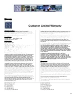
Warranty. 


Customer Limited Warranty


GATEKEEPER SYSTEMS INC. (Company) warrants that any product 
manufactured or supplied by Gatekeeper Systems and found in the reasonable 
judgment of Gatekeeper Systems to be defective in material or workmanship will be 
repaired or replaced by Gatekeeper Systems without charge for parts and labor. 
 
This warranty shall cover the following periods and equipment: 

Camcorder System  
Cameras - 1 year           Battery Adapters - 1 year 
Plates & Enclosure Boxes – lifetime 
 
Gatekeeper System  
Interior Cameras - 5 years 
Exterior Cameras - 1 year 
VCR - 1 year 
GSX-900 / 1000 Digital Recorder - 1year 
NiTRO

-900 / 1000 Digital Recorder – 5 years (hard drives limited to 3 years) 

NiTRO

 401 and NiTRO

 404 Digital Recorder – 3 years 

NiTRO-X 401 and NiTRO-X 404 Digital Recorder – 3 years 
304SD Digital Recorder – 3 years 
Kingston SDHC Memory Card – Lifetime 
Lexar SDXC Memory Card – 10 Years 
Gatekeeper SD Cards – 5 years 
All Accessories and Other Products Not Identified above - 1 year 
 
The warranty periods commence on the date of shipment. During the period of the 
warranty the Company, at its discretion will repair and/or replace all improperly 
functioning equipment caused by a manufacturer’s defect. This warranty does 
not protect against accidental or intentional damage, vehicle electrical systems 
generating steady state or transients, voltages or currents exceeding product 
specification, loss, acts of nature, water damage, or any other event that did not 
originate during the manufacturer of the product. DVR’s must be returned once 
every twelve months for service otherwise warranty may be void. 

The Gatekeeper Systems product including any defective part must be returned to 
Gatekeeper Systems within the warranty period. The expense of delivering 
Company product to Gatekeeper Systems for warranty work will be paid by the 
customer. The expense of delivering Company product back to the customer will 
be paid by Gatekeeper Systems. Gatekeeper Systems’ responsibility in respect to 
claims is limited to making the required repairs or replacements and no claim of 
breach of warranty shall be cause for cancellation or rescission of the contract of 
sale. Proof of purchase complete with the serial numbers of the products 
purchased will be required by the customer to substantiate any warranty claim. 
All warranty work must be performed by an authorized Gatekeeper Systems 
service representative. 

This warranty does not cover any Gatekeeper Systems’ product that has been 
subject to misuse, neglect, negligence, or accident, or that has been operated in any 
way contrary to the operating instructions as specified by Gatekeeper Systems 
either verbally, in writing, by instructions written on the product or in the 
Gatekeeper Systems Installation and Operating Manual. This warranty does not 
apply to any damage to the Gatekeeper Systems product that is the result of 
improper maintenance or to any   


Gatekeeper Systems’ product that has been altered or modified so as to adversely 
affect the products’ operation, performance or durability or that has been 
altered or modified so as to change its intended use. Gatekeeper Systems’ is not 
responsible for lost or missing video. 
 
The warranty does not extend to repairs made necessary by normal wear or by 
the use of parts or accessories which are either incompatible with the Company 
product or adversely affect its operation, performance or durability. 

Gatekeeper Systems reserves the right to change or improve the design of any 
Company product without assuming any obligation to modify any product previously 
manufactured. 

ALL IMPLIED WARRANTIES ARE LIMITED IN DURATION TO THE SPECIFIED PERIOD FOR 
EACH PRODUCT CATEGORY AS LISTED IN THIS DOCUMENT. ACCORDINGLY, ANY 
SUCH IMPLIED WARRANTIES INCLUDING MERCHANTABILITY, FITNESS FOR A 
PARTICULAR PURPOSE, OR OTHERWISE, ARE DISCLAIMED IN THEIR ENTIRETY AFTER 
THE EXPIRATION OF THE APPROPRIATE WARRANTY PERIOD. GATEKEEPER 
SYSTEMS’ OBLIGATION UNDER THIS WARRANTY IS STRICTLY AND EXCLUSIVELY 
LIMITED TO THE REPAIR OR REPLACEMENT OF DEFECTIVE PARTS, AND GATEKEEPER 
SYSTEMS DOES NOT ASSUME OR AUTHORIZE ANYONE TO ASSUME FOR THEM ANY 
OTHER OBLIGATION. 

GATEKEEPER SYSTEMS ASSUMES NO RESPONSIBILITY FOR INCIDENTAL, 
CONSEQUENTIAL OR OTHER DAMAGES INCLUDING, BUT NOT LIMITED TO THE 
EXPENSE OF RETURNING THE COMPANY PRODUCT TO GATEKEEPER SYSTEMS 
CORPORATE HEAD OFFICE, MECHANIC’S TRAVEL TIME, CUSTOMER LABOR EXPENSES, 
TELEPHONE OR TELEGRAM CHARGES, RENTAL OF LIKE PRODUCT DURING THE TIME 
WARRANTY SERVICE IS BEING PERFORMED, TRAVEL, LOSS OF USE OF THE 
PRODUCT, LOSS OF TIME OR INCONVENIENCE. 

Warranty Service 

To obtain warranty service, the purchaser must notify the Company during the 
warranty period. The Purchaser will discuss the defect or problem with a Company 
technician, and once the problem has been verified the Company will issue a return 
material authorization number (RMA) authorizing the purchaser to return faulty 
merchandise to the Company for repair or replacement as determined by the 
Company. It may be necessary for the customer to assist Gatekeeper Systems in 
assessing failed product. Gatekeeper Systems may require the customer to remove 
hardware, manipulate software and/or perform other diagnostic activities. Failure 
to assist in and allow remote diagnostic activities may result in a service fee being 
charged. 

Advance replacements will be issued for the first 45 days from the date of shipment. 

This Warranty applies to all Company products manufactured by Gatekeeper 
Systems and sold in the United States and Canada. 

This warranty gives you specific legal rights, and you may also have other rights which 
vary from state to state. 

 
USA RECEIVING FACILITY: 
Gatekeeper Systems Inc. 
446 Harrison Street 
Sumas WA 98295 
Tel. 1.604.864.6187 
Fax 1.604.864.8490 
Toll Free (N.A.) 1.888.666.4833 


CANADA OPERATIONS:  
Gatekeeper Systems Inc. 
301-3 1127 Wheel Avenue 
Abbotsford BC V2T 6H1 
Tel. 1.604.864.6187 
Fax. 1.604.864.8490 
Toll Free (N.A.) 1.888.666.4833 


Summary of Contents for 816-HD

Page 1: ...DN2778_816HD_UserGuideManual 2014 02 25 1 Safety Security Peace of Mind 816 HD USER GUIDE AND MANUAL...

Page 2: ...g the System 11 Installation Environmental Requirements 11 Power Connector CAB0000333 12 Sensors 12 GPS 13 Driver Alert Button 13 Using the COMRAD Docking Station 14 Using the Remote Control 16 Numeri...

Page 3: ...NT 31 SENSOR 31 ALARM OUTPUT 31 SPEED 32 ACCELERATION 32 TEMPERATURE 33 CAMERA 33 VOLTAGE 33 EMERGENCY EVENT 33 FATIGUE DRIVING 34 PERIPHERAL 34 PTZ 34 EXT COM 34 SYSTEM INFORMATION 34 SYSTEM 34 HISTO...

Page 4: ...layback 43 Sensor Alarm Playback 1 43 Sensor Alarm Playback 2 44 Vehicle Speed Playback 44 Clips 44 Saving a Clip 44 Exporting a Clip 46 Export to an AVI File 46 Blurring an Image 47 APPENDIX 48 Camer...

Page 5: ...TINGS ACTIONS 31 FIGURE 15 SPEED 32 FIGURE 16 ACCELERATION 32 FIGURE 17 EMERGENCY EVENT 33 FIGURE 18 SYSTEM INFO 34 FIGURE 19 MODULES 35 FIGURE 20 G4 INCIDENT MANAGEMENT SOFTWARE INTERFACE 38 FIGURE 2...

Page 6: ...al work install service or remove a DVR installing a backup camera system for example on a customer vehicle shall ensure that the battery in the vehicle is disconnected before work commences Customers...

Page 7: ...available from www gatekeeper systems com when released are system specific firmware updates must only be applied to the 816 HD system If this firmware is applied to any other Gatekeeper Systems DVR w...

Page 8: ...816 HD Digital Video Recorder Sensor Cable P N CAB000323 Power Cable P N CAB000333 Key Power Line Fuse Ignition Line Fuse CABLE GUARD Fastening Screws 2 PER UNIT CAB000310 Camera Adapter Cable 816 HD...

Page 9: ...wnload Kit Part Number G4 8XXHDDLK Contains Remote Control G4 S28 HDD READER CD with G4 Viewer RC150 Cable single RCA male to male CAB000362 Video Out Aviation Connection to RCA CAB 000157 Video Align...

Page 10: ...ators HDD When illuminated indicates that a COMRAD is present SD Displays if a SD card is present in the system GPS Illuminated when GPS signal is present NET Displays Network activity HTR When illumi...

Page 11: ...ure a regulated consistent power source is available for the 816 HD 2 DO NOT remove any enclosures covers associated with the 816 HD as this will void the warranty 3 Remove the In Line Power fuse prio...

Page 12: ...HD Ensure that the provided 1 AMP In Line fuse is used Positive C Red Connect to the positive terminal of the battery 12V Ensure that the provided 15 AMP In Line fuse is used Sensors The 816 HD allow...

Page 13: ...river Alert Button A Driver Alert Panel is available as an optional accessory for the 816 HD The Driver Alert Panel must be installed using the provide Tek screws The Driver Alert allows for the drive...

Page 14: ...ion Align the Alignment key located on the right hand side of the COMRAD Docking Station when looking at the back on the COMRAD Docking Station to the Alignment Key Slot on the COMRAD and push the two...

Page 15: ...hen G4 Incident Management Software is launched underneath the HDD heading the connected COMRAD COMRAD Docking Station will appear Please note that even if the COMRAD has two internal Hard Disk Drives...

Page 16: ...ne by one Figure 5 Remote Control Numeric Keypad 0 9 keys When used during setup number keys are used to key in values For viewing channels 1 2 3 and 4 use 1 2 3 and 4 on numeric keypad respectively k...

Page 17: ...the required date of the video you wish to search for Dates which have recorded video will be highlighted in Green Once the selections have been made highlight SEARCH and press enter on the remote con...

Page 18: ...mote control to enter the required date for the Event File required Figure 7 Event Search IO ALARM Displays Alarms triggered by Stop Arm Warning Lights Brake etc These Alarms are configured in System...

Page 19: ...t GPS An approved GPS module must be connected Once GPS has been selected and the option SAVED there may be a slight time delay as the system sync s with the GPS satellites NTP Reserved for future dev...

Page 20: ...omatically downloaded to the external USB drive Once a USB drive has been connected to the front of the 816 HD press the F1 button on the remote control to initiate auto download The USB device must b...

Page 21: ...configuration 1 Log In to The Gate section of www gatekeeper systems com and download the correct firmware for the GSI 816 HD system Please refer to the appropriate firmware Release Notes for specifi...

Page 22: ...stating Password Inconsistent This message will remain until the confirm password box has been completed and the OK button at the bottom of the screen has been selected USER When set to ON and USER en...

Page 23: ...vent When an Event has been triggered the 816 HD will record To set an Event to record go to System Settings Event to set triggers Default General Normal Rec Rate Options Normal or I Frame Normal The...

Page 24: ...ORDING SWITCH Options ON OFF When set to ON allows for EVENT based recording to capture a set amount of time ALARM PRE REC TIME prior to when the EVENT was generated ALARM PRE REC TIME 1 60 MIN Determ...

Page 25: ...available using Live View IP Intercom is currently reserved for future development It is recommended that LIVE AUDIO be left at its default value of OFF NEXT PAGE Displays options for CAMERAS 9 throug...

Page 26: ...CHEDULE DATE OPTIONS Single Day EVERY WKD Select a day of the week for the schedule to run Applies a schedule to every day of the week Runs the schedule based on the days selected in Workday From Susp...

Page 27: ...t of the 816 HD and 2 as part of the DB44 cable camera fly lead for initial setup and configuration CP3 is an internal name for the ICD which is an accessory available from Gatekeeper Systems also use...

Page 28: ...Address The MAC address of the 816 HD Figure 12 Local Network Settings SERVER The IP address shown are for example only Please consult with your I T department for all required information relating to...

Page 29: ...e the internal Wi Fi module for communications MESSAGE SERVER OPTIONS Domain Name If a fully qualified domain name is available this option can be utilized Enter the FQDN in the text entry box below t...

Page 30: ...ecomes active once the PASSWORD ENABLE option has been chosen Enter the required ESSID network name for the wireless network Figure 13 WI FI Settings PASSWORD ENABLE Options NONE WEP WPA MOBILE NETWOR...

Page 31: ...Alarm determines if the Alarm LED will flash when the Sensor is activated LOCK sets if the recorded video file created by the sensor will be protected from being over written On the second page of Sen...

Page 32: ...nd set to ON Next for either LOWSPEED or OVERSPEED set the THRESHOLD value Use the Numeric keypad on the remote control to set the required values To have an Alarm be registered when the THRESHOLD val...

Page 33: ...uminated if video loss occurs Please note that if no cameras are physically connected to the 816 HD but the corresponding channels have been Enabled VLOSS will display on the OSD Recorded Video and is...

Page 34: ...FORMATION There are Three sub menu s listed under the System Information Menu System History Modules SYSTEM In the System sub menu the System Info dialog box will display relevant information in regar...

Page 35: ...by the vehicle and also the Lowest Voltage since the last time this value was cleared To Clear a value use the remote control to highlight the word Clear to the Right of the relevant section and then...

Page 36: ...ng finding an incident easier than ever before INSTALLATION PLEASE NOTE The installation of G4 Viewer must be completed with Administrator rights For more information on this please speak with your Sc...

Page 37: ...Create a Desktop Icon and click Next A window stating Ready To Install will appear click on Install An Install Progress window will appear Once Setup has completed the Completing The G4 Viewer Setup W...

Page 38: ...from the COMRAD 5 Directory Displays all files clipped from a COMRAD and saved to that directory 6 Device Used in conjunction with a Gatekeeper Systems Wireless System 7 Displays options based on whic...

Page 39: ...playing in the video playback window Directory The Directory contains all of the previously Clipped video Once a clip has been made the Directory automatically updates to reflect the new clip name and...

Page 40: ...ening Screen Icons Once a video has been selected and playback has begun it is possible to search by specific criteria Click on the Search button just below the Search Icon 4 in Figure 21 This will la...

Page 41: ...e highlighted Playback Details Playback Details displays information about the currently playing Video file The Bus Name from where the video file has been loaded is located top left of Playback Detai...

Page 42: ...video files and selecting them for playback Note only one of the files in the folder in question needs to be highlighted and selected for all of the files in that folder to be played back Layout When...

Page 43: ...This will load the video into the Video Playback window and the Time Line will populate displaying the start time of the recorded video The selected video will now begin playing Figure 26 Playback Se...

Page 44: ...of the vehicle in the playback window will fluctuate with this box moving up Figure 28 Speed Playback and down the column matching the peaks and troughs of the Green indicators in the Time Bar Clips U...

Page 45: ...right of the Time Bar This will confirm the clip length 5 Once the has been selected a confirmation window will appear showing The clip Length 1 Required Video Channels 2 Video Clip Directory 3 Ensur...

Page 46: ...r several minutes depending upon the length of the exported file Once this has completed the dialog window will change stating Clip Finished when OK is clicked the default Folder will be automatically...

Page 47: ...t hand corner of the playback window arrowed in the image to the right This will bring up the Mosaic Setting Window Figure 31 Blurring an Image The Mosaic Setting window is divided into a 20 X 20 grid...

Page 48: ...with each camera and cut a small notch in the rubber pad to accommodate the camera cable The audio hole on the front of the camera can be used as an aiming guide for the direction the camera needs to...

Page 49: ...pping screws to fix the camera base to the vehicle 5 Connect the Camera Ball Molex connector to the connector at the end of the camera harness Hold the Camera Ball firmly against the Base Plate with t...

Page 50: ...tion Wire Routing Camera harness to be connected through opening in base Use existing wire paths wherever possible radio speakers etc Avoid excessively tight bends especially around metal surfaces Alw...

Page 51: ...51 Typical System Wiring Setup...

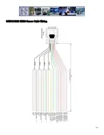
Page 52: ...52 CAB000323 DB26 Sensor Cable Wiring...

Page 53: ...the result of improper maintenance or toany Gatekeeper Systems product that has been altered or modified so as to adversely affect the products operation performance or durability or that has been alt...

Page 54: ...ion GSI Canada 301 31127 Wheel Avenue Abbotsford BC V2T 6H1 Canada GSI USA 446 Harrison Street Sumas WA 98295 USA Sales Technical Support North America Tel 1 604 864 6187 Fax 1 604 864 8472 Toll Free...

Reviews: