


13
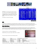
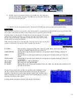
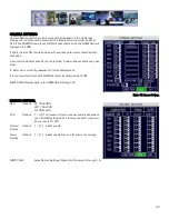
SENSOR’S 1-6 are inputs. In the example on the right
S1 has been set up for Brakes; S2 for Warning Lights.
Using the On-Screen menu go to SETTINGS
EVENT
SENSOR, enable the required sensors for the install,
make sure the alarm switch is ON for each required
sensor.
Once Sensors have been set, Click SAVE.
Figure 4: Sensor Setup.
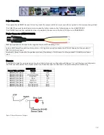
GPS
The 816-HD can be outfitted with an optional GPS module. For optimum results it is recommended that the GPS module be
exterior mounted utilizing the magnetic base with the cable protected by a suitable grommet. If it is not possible/practical to have
the GPS module exterior mounted, the GPS module must be mounted internally with a direct line of sight vertically skyward.
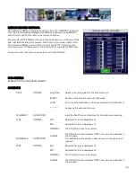
Driver Alert Button.
A Driver Alert Panel is available as an optional accessory for the 816-HD. The Driver Alert Panel must be installed using the
provide Tek screws. The Driver Alert allows for the driver of the vehicle to press the button and mark the recorded video with an
Alert. This makes searching for Alerts far faster and easier as G4 viewer can be set to display Alarms/Alerts.
The Driver Alert Panel is connected to CAB000323.
CAB000323 has two bundles of wires labeled 485–3 and 485-4.
Connect the Driver Alert Panel to bundle 485-3 as follows:
CABLE
CABLE
PERIPHERAL
EXT. COM SETUP
CAB000323
DRIVER ALERT CABLE
Mode
BUS
RED +5V
RED 5V
COM1
NONE (232-1)
BLACK GND
BLACK GND
COM2
NONE (232-2)
BROWN 485A
WHITE 485A
COM3
CONTROL PANEL (485-3)
BROWN/WHITE 485B
GREEN 485B
COM4
NONE
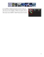
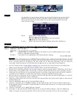
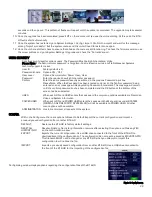
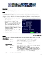
The Driver Alert Panel requires setting up in the configuration of the 816-HD. Navigate to Settings
Peripheral
Ext.Com Setup.


