


13
of the screen. Once the dock
configuration is uploaded, the “Set
Config” button will be enabled. Once
changes are made, click on the “Set
Config” button to save the new settings.
Calibration
values shown in the Gas Values
columns must match those appearing
on the calibration gas cylinder(s) that
will be used to calibrate the detector.
Non-matching calibration gas and
calibration gas value settings will lead
to inaccurate and potentially
dangerous readings.
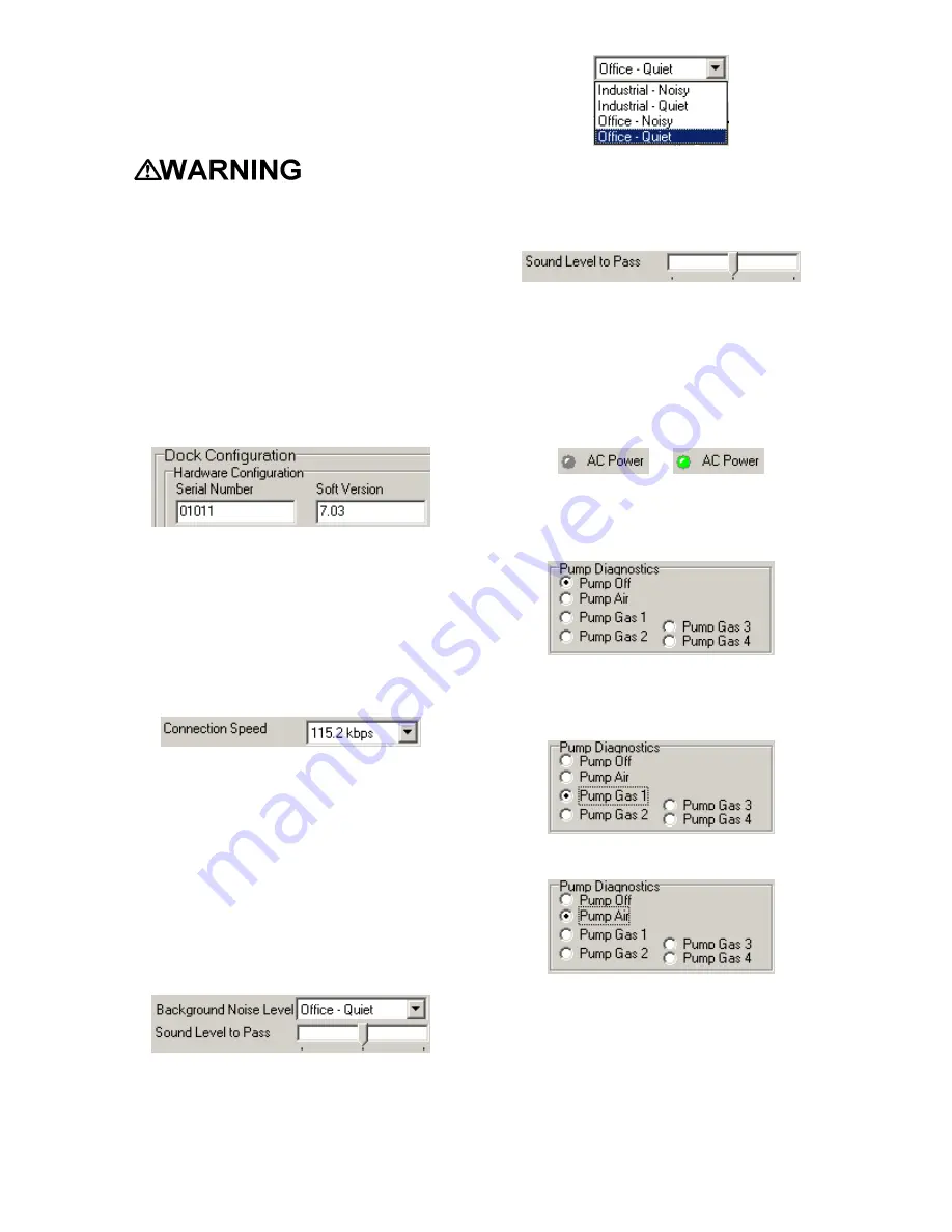
Hardware Configuration
The hardware configuration section
contains the serial number and software
version number of the dock at the upper
left corner.
This information may not be changed
with the software. Software updates will
cause the software version to change.
Connection Speed
The IrDA connection speed is given
below the serial number and software
version. The default connection speed is
38.4 kbps, although settings from 2400
bps to 115.2 kbps are available.
Sperian Instrumentation recommends
leaving the connection speed at the
default setting unless you are
experiencing frequent communication
problems in the form of a loss of
connection. If connection is frequently
lost, adjust the connection speed down
gradually until the problem is resolved.
Audible Alarm Sensitivity Controls
The audible alarm sensitivity controls
allow the user to customize the audible
alarm test criteria.
The Background Noise Level adjustment
offers four levels of background noise
levels. For the best results, select the
one that most closely approximates the
background noise level expected during
testing.
The Minimum Sound Level setting
determines the minimum amount of
sound required to pass the alarm test.
The higher the setting, the louder the
alarm will need to be to pass the test.
AC Power
The AC Power indicator is located
directly beneath the connection speed
setting. If the dock is being powered by
the USB cable, the AC Power will appear
grey. When the dock is being powered
by an AC power source, the AC Power
indicator will appear green.
or
Pump Diagnostics
Pump settings are controlled through the
Pump Control section on the Dock
Settings page.
Click “Pump Gas” along with the port
number to draw span calibration gas
through the right gas port at the back of
the dock.
Click “Pump Air” to draw the fresh air
sample through the Air input port.
The pump will run until “Pump Off” is
selected.
LCD Contrast Control
At the right side of the Dock
Configuration box is the LCD (Liquid
Crystal Display) Contrast Control.


