USE AND MAINTENANCE
70
ENGLISH
g
cod. G19502661
4.7 ROW MARKER DISK ADJUSTMENT
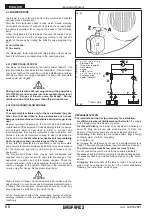
The row marker is a machine that traces a reference line parallel
to the tracks of the tractor on the ground.
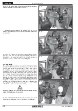
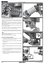
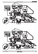
Once the tractor has completed its run and it has turned around,
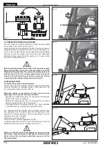
follow the reference row with one of the centre of the tractor (L,
Fig. 71). The row marker arms reverse themselves independently
and this reversal is actuate by the comand of the oildynamic
distributors of the tractor. When the system is not in use, protect
the quick coupling with its cap.
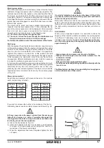
ATTENTION
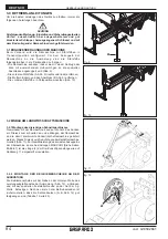
Before operating the hydraulic system of the row marker, apply
light pressure with your hand on the row marker arm in the
direction of the arrow (Fig. 72), unhook the safety devices on
both the arms (A Fig. 72), and then position them as shown in
Figure 73. For travel on the road, lock the row marker arms in
a vertical position with the safety devices (A Fig. 72).
SYSTEM REGULATION
The hydraulic system is supplied oil-free.
For this reason, before using the machine, make sure that all the
hydraulic cylinders are engaged slowly in both directions until
the piping and cylinders are filled with oil.
When the system is operated for the first time and at the
beginning of each season, proceed as follows
:
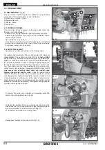
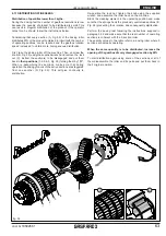
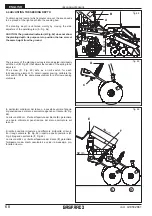
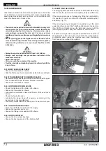
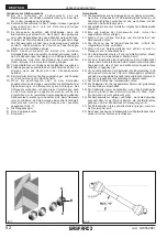
- Keep the row marker closed (Fig. 74) and remove the plug (det.
B) from both hydraulic cylinders.
- Release the safety devices (Fig. 72) and open the row marker
arms manually until they sit on the ground.
- Fit the plugs back on the cylinders (det. B, Fig. 75) and close the
row marker arms by engaging the hydraulic system.
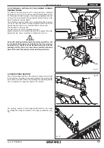
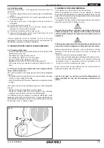
The hydraulic systems provided come equipped with one-way
flow regulators (Fig. 68) which allow for the regulation of the
quantity of oil during opening or closing, depending on how the
regulators have been installed:
Flow from A to B, free (Fig. 68);
Flow from B to A, choked (regulated) (Fig. 68).
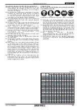
o regulate, loosen the lock nut (1) and turn the knob (2). Once this
adjustment has been made, re-tighten the lock nut.
WARNING
Make sure that the result of this adjustment does not cause
the rising or descent speed to damage the structure itself.
Never exceed the maximum admissible pressure for the
hydraulic system.
fig. 72
fig. 73
A
A
C
D
L
fig. 71
fig. 74
fig. 75
B
B
Summary of Contents for ALIANTE DD
Page 4: ...cod G19502661 g 4...
Page 38: ...cod G19502661 g 38 Notes...
Page 39: ...39 cod G19502661 g Notes...
Page 40: ...cod G19502661 g 40...
Page 74: ...cod G19502661 g 74 Notes...
Page 75: ...75 cod G19502661 g Notes...
Page 76: ...cod G19502661 g 76...
Page 110: ...cod G19502661 g 110 Notes...
Page 111: ...111 cod G19502661 g Notes...
Page 112: ...cod G19502661 g 112...
Page 146: ...cod G19502661 g 146 Notes...
Page 147: ...147 cod G19502661 g Notes...
Page 148: ...cod G19502661 g 148...
Page 182: ...Notes...

