background image

    Adjustment 

—————————— 


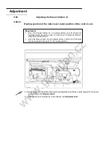
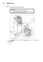
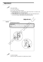
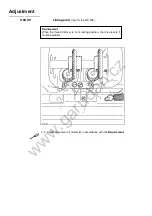
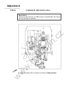
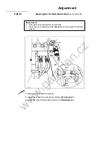
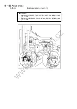
  Disconnect air supply of the air filter/ lubricator. 

  Move unit 

1

 by hand as far as possible to the right. 

  Adjust bracket 

2

 (screws 

3

) according to 

Requirement 1

  Move unit 

1

 by hand as far as possible to the left. 

  Adjust screw 

4

 (nut 

5

) according to 

Requirement 2


    Adjustment 

—————————— 

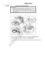
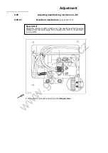
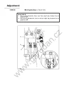
9.05.05 


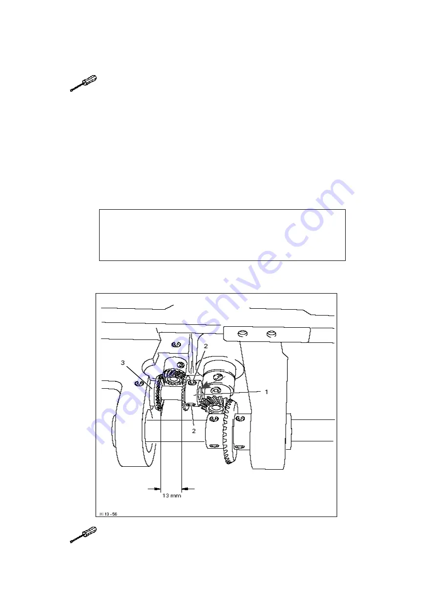
Bevel gears for feed wheel drive

 (on the GP-710)


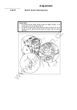
  Adjust bevel gear 

1

 (screws

 2

) according to 

Requirement 1

  Adjust bevel gear 

3

 (screws 

4

) according to 

Requirement 2.


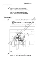
Requirement 

1.  the right side of bevel gear 

1

 must be flush with its drive shaft (see 

arrow). 

2.

  there must be a distance of 

13 mm

 between bevel gear 

3

 and bevel 

gear 

1

.


www.garudan.cz

Summary of Contents for GP-710-148

Page 1: ...top cutout 6 4 6 05 Mounting the table top 6 5 7 Preparation 7 1 7 01 Inserting the needle on model GP 710 7 1 7 02 Inserting the needle on model GP 724 7 2 7 03 Winding the bobbin thread adjusting t...

Page 2: ...03 18 Synchronization of roller presser and feed wheel 9 25 9 03 19 Retainer only on model GP 724 9 26 9 03 20 Knee lever 9 27 9 03 21 Needle and tension release 9 28 9 03 22 Thread check spring GP 7...

Page 3: ...available to the operating personnel at all times The Instruction Manual must be read before operating the machine for the first time The operating and specialist personnel must to be instructed in th...

Page 4: ...ible Never reach into the sewing area while sewing Danger of injury by the needle Never leave objects on the table while adjusting the machine settings Objects can become trapped or be slung away Dang...

Page 5: ...n of the take up lever On machines with thread lubricator only operate the machine with the eye guard 3 lowered The eye guard 3 protects the eyes from oil particles from the thread lubrication Do not...

Page 6: ...ynchronized needle The machines are used for sewing lockstitch seams in the leather and upholstery industries Any use of these machines which is not approved by the manufacturer shall be considered as...

Page 7: ...data Operating voltage 230 V 10 50 60 Hz Max power consumption 1 2 kVA Fuse protection 1 x 16 A insert Noise data Emission sound level at the work place at appropriate speed DIN 45 635 48 A 1 ISO 112...

Page 8: ...l equipment Subclass D Automatic edge trimmer Subclass D3 Automatic edge trimmer automatic presser foot lifter backtacker Nm GP 710 GP 724 1 100mm 40 3 90 134 134 35 Model Thread thickness Nm max Need...

Page 9: ...to be carried out or important information is accentuated by symbols which have the following meanings Note information Cleaning care Lubrication Maintenance repairs adjustment servise work only to b...

Page 10: ...nitoring with stitch counting Machines without D3 About 100 stitches before reaching the preset number of stitches LED 1 Flashes After the thread has been trimmed and the bobbin changed The stitch cou...

Page 11: ...r1 5 05 Knee lever The roller presser can be raised by pressing the knee lever 1 in the direction of the arrow 5 06 Key for setting stitch length The stitch length is set by pressing key 1 and turning...

Page 12: ...5 07 Swing out roller presser When the roller presser is raised it can be swung out by pulling it lightly downwards w w w g a r u d a n c z...

Page 13: ...during sewing 6 01 Installation The site where the machine is installed must be provided with suitable connections for electric current It must be ensured that the standing surface of the machine sit...

Page 14: ...stand l Fit the reel stand as shown in Fig Afterwards insert the stand in the hole of the table top and secure it with the nuts provided 6 02 02 Fitting the tilt lock 6 02 03 Fitting the machine cover...

Page 15: ...6 02 04 Mounting the flange motor to the bearing plate 6 02 05 Mounting the flange motor to the machine w w w g a r u d a n c z...

Page 16: ...Mounting the belt guard of the flange motor In this position fit toofhed belt 1 Swing the bearing plate 2 of the motor so that the toothed belt is tensioned In this position tighten screws 3 w w w g...

Page 17: ...operated under any circumstances The machine only be connected to an earthed socket When the machine is running the balance wheel must turn towards the operator If it does not the motor connection mu...

Page 18: ...6 Installation and commisioning 6 04 Tilted work base 6 05 Tilted work base 6 4 w w w g a r u d a n c z...

Page 19: ...6 06 Mounting the table top w w w g a r u d a n c z...

Page 20: ...removing the plug from the electric power socket 7 01 Inserting needle on model GP710 108 Switch the machine off Danger of injury if the machine is started accidentally Only use needles of system 134...

Page 21: ...needle depends on the model of the machine and the thread ad material used see Chapter 3 02 Needles and threads 7 03 Winding the bobbin thread adjusting the primary thread tension Place an empty bobb...

Page 22: ...se latch 1 and remove bobbin case 2 Inserting bobbin case l Insert bobbin case 2 Close the latch and close the post 7 05 Insert the bobbin into the bobbin case 1 Pass the thread through the slot under...

Page 23: ...Swith the machine off Danger of injury if the machine is started accidentally Tilt up the eye guard 1 Thread the needle thread as shown in Fig 9 06 On model H961 the needle is threaded from left to t...

Page 24: ...off Danger of injury if the machine is started accidentally Tilt up the eye guard 1 Thread both needle threads as shown in Fig 9 07 The left needle is threaded from right to the left and the right ne...

Page 25: ...he same time turn the balance wheel until the stitch setter clicks into position Hold down key 1 and turn the balance wheel to and fro until the stitch length required is shown on the scale 2 opposite...

Page 26: ...the machine off Disconnect the air hose at the air filter lubricator Draining woter bowl 1 Water bowl 1 drains itself automatically when the compressed air hose is disconnected from the air filter lub...

Page 27: ...t position Open the post cap and remove the bobbin case cap and the bobbin Unscrew hook gib 1 Turn the hand wheel until the point of bobbin case 2 penetrates into the groove of the hook race approx 5m...

Page 28: ...e arrow 8 05 Check the oil level before each use There must always be oil in reservoir 1 If required refill oil through hole Use only oil with a mean viscosity of 22 0 mm2 s at 40 C and a density of 0...

Page 29: ...nto the support Fig shows the bevel gears of the GP 724 Apply grease to all the tooth flanks and the rack see arrows To set the sewing head upright press tilt lock 1 backwards and set the sewing head...

Page 30: ...the text The order of the following chapters corresponds to the most logical work sequence for machines which have to be completely adjusted If only specific individual work steps are carried out both...

Page 31: ...on on the GP 710 Set the minimum stitch length Adjust needle bar screw 1 according to the Requirement Requirement With the stitch length set at its minimum the needle should be positioned in the centr...

Page 32: ...n in sewing direction on the GP 724 Ajust needle bar screws 1 and 2 according to the Requirement Requirement The needle should be positioned in the centre of the needle hole as seen in the direction o...

Page 33: ...needle height Adjust needle bar 1 screw 2 Without turning it according to the Requirement Requirement When the needle bar is at top dead centre there must be a clearance of approx 21mm between the ne...

Page 34: ...the needle bar positioned 2 0 mm after bottom dead centre on both hooks 1 the hook point must be at needle centre with a hook to needle clearance of 0 05 to 0 1 mm 2 the top of the needle eye must be...

Page 35: ...according to Requirement 1 and tighten screw 8 Tighten screws 1 and 6 Making sure that there is some play in the bevel gear tighten screws 3 and 5 With retaining collar 10 touching bevel gear 11 tight...

Page 36: ...bar positioned 2 0mm after bottom dead centre and the stitch length set at 0 8 1 the hook point must be at needle centre with a hook to needle clearance of 0 05 to 0 1mm 2 the top of the needle eye m...

Page 37: ...djust needle height according to Requirement 2 Adjust hook post according to Requirement 1 and tighten screw 4 Making sure that there is some play in the bevel gear tighten screws 2 With retaining col...

Page 38: ...sewing direnction on the GP 724 Shift bearing plate 1 screws 2 on both sides of the post according to the Requirement Requirement As seen crosswise to the sewing direction the needles must penetrate i...

Page 39: ...e to sewing direnction on the GP 710 Adjust feed wheel post 1 screws 2 3 and 4 according to the Requirement Requirement As seen crosswise to the sewing direction the needle must penetrate in the centr...

Page 40: ...dges of the bobbin case opener 1 and bobbin case 3 should be on one level 2 when the bobbin case opener 1 has deflected the bobbin case to its furthest point the catch of the bobbin case should be fro...

Page 41: ...n case opener has deflected the bobbin case to its furthest point Adjust bobbin case opener 1 screw 2 in accordance with Requirement 2 On the GP 724 these adjustments must be repeated on the right pos...

Page 42: ...724 Requirement 1 when pressure is applied to the feed wheel 4 it should protrude from the needle plate by tooth height approx 0 8mm 2 when no pressure is applied to the feed wheel 4 it should have a...

Page 43: ...see that the teeth of drive wheel 3 and feed wheel 4 lock into each other properly Tighten screws 1 Adjust guide 5 according to Requirement 2 and tighten screws 2 Adjustment 61 035 9 03 10 Height of t...

Page 44: ...h length Turn stitch length control device 1 screws 2 according to Requirement Requirement When the needle with maximum stitch length set coming from top dead centre is 3 mm above the needle plate the...

Page 45: ...disk 1 screw 2 according to the Requirement Requirement When the stitch length control device is locked in position and the maximum stitch length is set the marking line of the highest number on the...

Page 46: ...length Twist or shift the shaft crank 1 screw 2 according to the Requirement Requirement When the maximum length is set the linkage rod 3 or lingkage rods 3 and 4 on the model 9625 and 9610 must be a...

Page 47: ...ngth Twist or shift the shaft crank 1 screw 2 according to the Requirement 61 040 Requirement When the maximum stitch length is set the linkage rods 3 and 4 must be able to move freely at their left a...

Page 48: ...bar lifter Adjust the presser bar 1 screws 2 according to the Requirement Make sure that the roller presser is parallel to the feed wheel Requirement When the presser bar lifter is raised the clearanc...

Page 49: ...quirement 3 When sewing very tight curves the roller presser 1 must be moved a little towards the operator Requirement When the roller presser 1 is touching the feed wheel 5 it must 1 be parallel to f...

Page 50: ...th on stitch length scale Requirement When the stitch length is set at 3 and after the needle has entered a strip of leather 11 times the total length from the first to last needle penetration must be...

Page 51: ...the Requirement Clamp 1 must not be positioned diagonally to the rock shaft Adjustment 9 03 18 Synchronization of roller presser and feed wheel Requirement After 30 needle penetrations in a strip of...

Page 52: ...tment 61 042 9 03 19 Retainer only on GP 724 Adjust retainer 1 screw 2 according to Requirement 3 Adjust bracket 3 screw 4 according to Requirenment 1 and 2 Requiement The retainer 1 must 1 be as clos...

Page 53: ...r 5 screws 6 according to Requirement 3 Requirement 1 before the roller presser rises the knee lever must still have a slight play 2 when the knee lever is raised as far as possible the lever for the...

Page 54: ...Adjustment 61 9 03 21 Needle thread tension release 61 043 Align tension mounting plate 1 and pressure plate 2 according to Reqirement w w w g a r u d a n c z...

Page 55: ...ead check spring 7 should be completed when the needle point penetrate the fabric spring stroke approx 7 mm 2 when the largest thread loop is formed while the thread is passed around the hook the thre...

Page 56: ...y turning screw 3 screw 4 Adjust the thread regulator 5 screw 6 acoording to Requirement 2 For technical reasons it may be necessary to deviate from the specified spring stroke or spring tension Move...

Page 57: ...springs 3 and 6 should be completed when the needle points penetrate the fabric spring stroke approx 7 mm 2 when the largest thread loop is formed while the thread is passed around the hook the thread...

Page 58: ...crew 8 Adjust support 9 screw 10 according to Requirement 1 If the adjustment range is too low support 9 can be screwed into another hole Adjust the thread regulator 11 screw 12 according to Requireme...

Page 59: ...equirement 2 Requirement 1 when the bobbin winder is engaged the winding spindle must be driven relilably When the bobbin winder is disengaged the friction wheel 5 must not be moved by drive wheel 1 2...

Page 60: ...Adjustment 9 03 25 Pressure of roller presser Adjust roller pressure with screw 1 according to the Requirement w w w g a r u d a n c z...

Page 61: ...Adjustment 9 03 26 Lubrication Requirement After a running time of 10 seconds a fine line of oil should form on a strip of paper held next to the hook w w w g a r u d a n c z...

Page 62: ...the machine run for 2 3 min While the machine is running do not place hands in the needle or hook area Danger of injury from moving parts With the machine running hold a strip of paper on the hook an...

Page 63: ...en the thread jams the coupling 1 disengages in order to avoid damage to the hooks A description of how to engage the coupling follows Remove jammed thread Hold coupling 1 with screw 2 and turn the ba...

Page 64: ...ws in accordance with Requirement 1 Adjust control cam 3 screw 4 in accordance with Requirement 2 Requirement 1 when the thread trimmer is in resting positon lever 5 should be touching piston 6 and th...

Page 65: ...screw 2 and move the toothed segment 4 by one tooth Requirement 1 there should be a minimum amount of play between toothed wheel 3 and toothed segment 4 2 both in the neutral position and the foremost...

Page 66: ...plate Move thread catcher 1 screws 2 two screws parallel to the thread catcher holder in accordance with the Requirement 61 100 Requirement During its swivel movement thread catcher 1 should not pass...

Page 67: ...ead catcher 1 must be parallel to the surface of the thread catcher holder 4 Requirement 1 the bottom edge of the thread catcher 1 should be at a distance of 0 1 mm from the positioning finger of the...

Page 68: ...n accordance with Requirement 1 or swivel it in accordance with Requirement 2 Requirement 1 the knife 1 should be touching the needle plate 2 the knife pressure should be set as low as possible but th...

Page 69: ...bobbin thread clamp spring should be guided reliably in the thread groove of the thread catcher 3 2 the tension of the bobbin thread spring clamp should be as low as possible but the bobbin thread sho...

Page 70: ...e machine and bring the take up lever to its bottom dead centre Engage and disengage the thread cather 3 by hand and check Requirement 1 Adjust if necessary Control requirement 2 After the thread has...

Page 71: ...roke it must not carry bobbin thread 3 forward too 2 when thread catcher 1 is in its front position bobbin thread 3 must be held reliably by hook 4 3 after the trimming action both the needle thread a...

Page 72: ...on of the thread catcher Check Requirement 3 and if necessary readjust the bobbin thread retaining spring 2 in according with Chapter 9 04 06 Bobbin thread retaining spring Adjustment 9 04 08 Releasin...

Page 73: ...Linkage rod only for the GP 724 Adjust drive levers 1 screw 2 in accordance with the Requirement Requirement When the thread trimmer is in its resting position the drive levers 1 must be parallel w w...

Page 74: ...le in needle hole only for GP 710 Turn crank 1 screw 2 according to the Requirement Requirement When the maximum stitch length is set the needle must be the same distance from the inside edge of the n...

Page 75: ...ing for roller presser drive Adjust coupling half 1 screw 2 according to the Requirement Requirement There must be a distance of 3 mm between coupling half 1 and locking disc 3 of the drive mechanism...

Page 76: ...unit 1 screws 2 Adjust bevel gear 3 screw 4 according to Requirement 1 Adjust beve gear 5 screw 6 according to Requirement 2 Requirement 1 bevel gear 3 must fit well on the left side 2 there must be a...

Page 77: ...el gear play on the GP 724 Requirement 1 when sewing forwards there must be a slight play between bevel gears 6 and 7 2 when sewing backwards there must be a slight play between bevel gears 6 and 8 w...

Page 78: ...t Adjust screw 4 nut 5 according to Requirement 2 Adjustment 9 05 05 Bevel gears for feed wheel drive on the GP 710 Adjust bevel gear 1 screws 2 according to Requirement 1 Adjust bevel gear 3 screws 4...

Page 79: ...Bevel gear play on the GP 710 Requirement 1 when sewing forwards there must be a slight play between bevel gear 6 and 7 2 when sewing backwards there must be a slight play between bevel gear 6 and 8...

Page 80: ...lubricator Move unit 1 by hand as far as possible to the right see arrow Adjust screw 2 nut 3 according to Requirement 1 Move unit 1 by hand as far as possible to the left see arrow Adjust screw 4 nu...

Reviews: