USER’S MANUAL
-
15
-
The floor must be flat and without gradients (maximum of
10 mm tolerance)
INSTALLING WITH EXPANSION ANCHORS
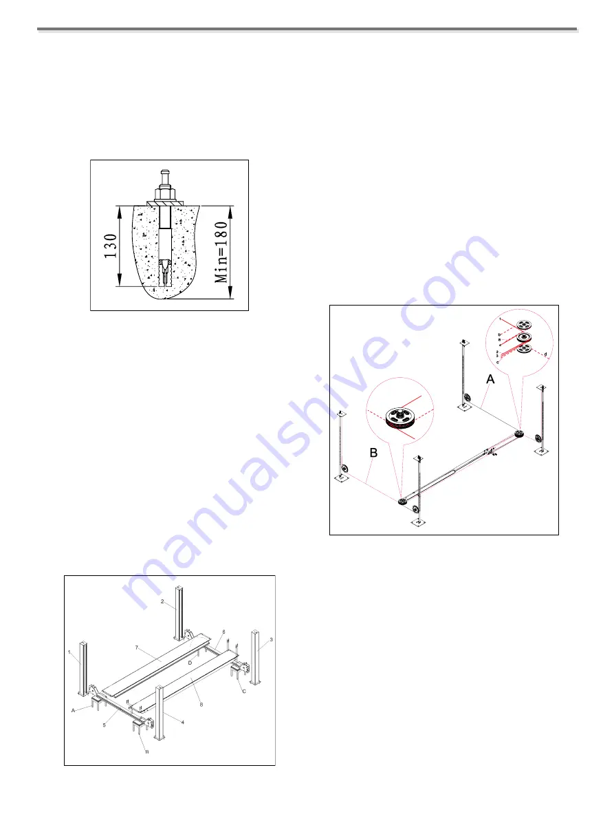
Example of installation on industrial floor in average mix
concrete with embedded electrowelded reinforcing mesh,
thickness min. 180 mm and properly leveled.
Fig. 30
PREPARING THE FLOOR - MARKING
The measurements shown in the figure are compulsory;
maximum tolerance is:
●
+/- 1 mm alignment
●
+/- 2 mm squaring
WARNING
UNAUTHORISED PERSONS MUST NOT BE
ADMITTED DURING ASSEMBLY OPERATIONS.
4.1 ASSEMBLY OF MOVABLE STRUCTURE
(PLATFORM)
Fig. 32
1 - Place 4 trestles of the same height and suitably sturdy to
hold 250 kg each, in the area where you intend to install the
lift. Position the trestles as shown in the
Fig. 32-A/B/C/D
.
2 - Remove the posts from the packing
(Fig. 32-1/2/3/4)
,
together with the movable platform
(Fig. 32-7)
, the
hydraulic power unit and accessories.
3 - Place the fixed platform
(Fig. 32-8)
on two trestles
(Fig. 32-B/C)
together with the two cross-pieces
(Fig. 32-
5/6)
.
4 - Place the cross-piece
(Fig. 32-5)
on trestle
(Fig. 32-A)
and secure it to the fixed platform
(Fig. 32-8)
.
During these operations check that the steel cables are
correctly positioned (Fig. 33).
Fig. 33
5 - Place the movable platform
(Fig. 32-7)
on the cross-
pieces
(Fig. 32-5/6)
.
6 - Check squaring and the diagonals of the cross-piece -
platform assembly; check also that the movable platform
runs smoothly between the cross-pieces; then, fully tighten
the screws securing the fixed platform.
Summary of Contents for TFA4500-3D
Page 2: ......
Page 4: ...USER S MANUAL ii...
Page 7: ...USER S MANUAL 3 Chapter 2 SPECIFICATIONS 2 1 OVERALL DIMENSION TFA4500 3D...
Page 8: ...USER S MANUAL 4 TFA5000 3D...
Page 9: ...USER S MANUAL 5 TFA5500 3D...
Page 10: ...USER S MANUAL 6 TFL5000 3D...
Page 31: ...USER S MANUAL 27 APPENDIX B HYDRAULIC DIAGRAM...
Page 32: ...USER S MANUAL 28 APPENDIX C ELECTRICAL WIRING DIAGRAM C 1 380V ELECTRICAL WIRING DIAGRAM...
Page 33: ...USER S MANUAL 29 C 2 220V ELECTRICAL WIRING DIAGRAM...
Page 35: ...USER S MANUAL 31 EXPLOSIVE DIAGRAM...
Page 36: ...USER S MANUAL 32...
Page 37: ...USER S MANUAL 33...


